
Instruction Manual

6 Introduction
StorCase Technology, Inc. S20A102 User's Guide - Rev. A01
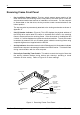
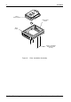
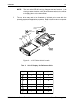
Figure 5: Receiving Frame (Rear View)
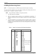
Enable Termination Power Connector (J4): This jumper is installed at the
factory and enables termination power to/from the SCSI bus.
NOTE: Do not remove this jumper!
Factory-Installed Jumpers (J3): There are two (2) jumpers factory-installed on
J3. One jumper is located on Pins 7 & 8, the other on Pins 9 & 10.
NOTE: Do not remove jumpers! (Remove only if attaching the DX1/200-
SWC160/RH Isolator/Repeater Board. Refer to Appendix B for further
information.)
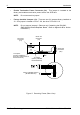
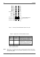
J3
J4
P1
DC Power
Connector
(P1)
J3 Jumpers
(Factory-Installed on
Pins 7 & 8 and Pins 9 & 10
Do Not Remove!)
68-Pin I/O
Connector
(J2)
Option Pin
Connector
(W1)
0456h
J4 Jumper
(Factory-Installed
Do Not Remove!)
17 18
19 20
Factory-Installed Jumpers
(Do Not Remove!)