StorCase® Technology Data Express® DE100 (P/N S20A102) Removable SCSI Wide Ultra160 Drive Enclosure User's Guide
i StorCase® Technology Data Express® DE100 (P/N S20A102) Removable SCSI Wide Ultra160 Drive Enclosure User's Guide Part No. D89-0000-0151 A01 April 2001 StorCase Technology, Inc. 17600 Newhope Street Fountain Valley, CA 92708-9885 Phone (714) 438-1850 Fax (714) 438-1847 S20A102 User's Guide - Rev. A01 StorCase Technology, Inc.
ii LIMITED WARRANTY STORCASE TECHNOLOGY, INC. ("StorCase") warrants that the following products will be free from defects in material and workmanship for a period of seven (7) years from the date of purchase from StorCase or its authorized reseller: all Data Silo®, Data Stacker®, and InfoStation external expansion chassis, all Data Express® removable device enclosures and all StorCase interface cables and accessories specifically intended for use with these products.
iii Disclaimers The foregoing is the complete warranty for the products identified above and supersedes all other warranties and representations, whether oral or written. StorCase expressly disclaims all warranties for the identified products which are not stated herein, including, to the extent permitted by applicable law, any implied warranty of merchantability or fitness for a particular purpose.
iv Declaration of Conformity Company Name: StorCase Technology, Inc. Corporate Office Address: 17600 Newhope Street Fountain Valley, CA 92708 Manufacturing Address: 3400 S.
v Table of Contents DATA EXPRESS DE100 INTRODUCTION ................................................................................. Packaging Information ................................................................................................... Serial Numbers ............................................................................................................... Package Contents .........................................................................................................
vi List of Figures Figure 1: Figure 2: Figure 3: Figure 4: Figure 5: Figure 6: Figure 7: Figure 8: Figure 9: Figure 10: Package Contents ............................................................................................... 2 DE100 Receiving Frame and Carrier .................................................................. 3 Receiving Frame Front Panel .............................................................................. 4 Receiving Frame Unit ID Number and Activity Display ...........
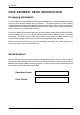
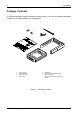
Introduction 1 DATA EXPRESS® DE100 INTRODUCTION Packaging Information The StorCase Technology Data Express® system is shipped in a container designed to provide protection and prevent damage during shipment. The Data Express unit was carefully inspected before and during the packing procedure at the factory. Bent or broken connectors, or evidence of other damage to the Data Express should be reported to the shipper immediately. Refer to Figure 1 for the package contents.
2 Introduction Package Contents The DE100 package contents include the following items. If any item is missing or damaged, contact your StorCase dealer for a replacement. 7 1 6 2 5 Da ta E ID Driv e Car Sele rier Disk (No Driv t Inclu e ded Pow ) er I/O Cab Cable le ct Cab le 3 xpr ess Cab Cov (Pro er le vide d) Driv Har e Phil 3/16 lipsdwareMountin Flat # 6-32(4ea g HD x ) 0151 Cab Scre le # Flat 6-32 ws (2Cover HD x 3/16plcs ) 4 1. 2. 3. 4.
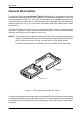
Introduction 3 General Description The StorCase Technology Data Express® DE100 (P/N S20A102) is composed of a receiving frame which supports most 68-pin SCSI Ultra160 (LVD) interfaces and fits within a 5.25" halfheight peripheral slot (Figure 2). This 16-bit I/O can support up to 160MB/sec transfer rates. The receiving frame contains one (1) removable drive carrier designed to provide durable and reliable mounting for one (1) 3.5" form factor, SCSI Wide, Wide Ultra, Wide Ultra2 or Wide Ultra160 drive.
4 Introduction Receiving Frame Front Panel Key Lock/Drive Power Switch- This key switch assures proper seating of the drive carrier within the receiving frame, turns power to the drive carrier on and off, and prevents unauthorized removal or installation of the carrier. For the computer to access data on the disk drive, the key must be turned counterclockwise to the locked position. The key may also be permanently attached to the locking mechanism as shown in Appendix C.
Introduction 5 Figure 4: Receiving Frame Unit ID Number and Activity Display Receiving Frame Rear Panel (Refer to Figure 5) I/O Connector (J2): The input/output connector provides a standard interface for 16-bit wide SCSI signals. DC Power Connector (P1): The Data Express uses a standard 4-pin DC power connector to accept DC power. I/O Connector (J2): The input/output connector provides a standard interface for 16-bit wide SCSI signals.
6 Introduction Enable Termination Power Connector (J4): This jumper is installed at the factory and enables termination power to/from the SCSI bus. NOTE: Do not remove this jumper! Factory-Installed Jumpers (J3): There are two (2) jumpers factory-installed on J3. One jumper is located on Pins 7 & 8, the other on Pins 9 & 10. NOTE: Do not remove jumpers! (Remove only if attaching the DX1/200SWC160/RH Isolator/Repeater Board. Refer to Appendix B for further information.
Installation 7 DE100 INSTALLATION Installing the Drive into the Carrier Preparation While performing the steps in this section, work on a soft surface to prevent excessive shock to the drive being installed. Also refer to the manufacturer's documentation provided with the drive. NOTE: A #2 Phillips screwdriver will be required during this procedure. 1. Remove the drive from its protective packaging. 2. Plastic Drive Bezel: If the drive came equipped with a plastic front bezel, it must be removed. 3.
8 Installation Drive (Not Included) Drive Carrier Board Drive Carrier 0151h #6-32 x 1/4 Phillips Flat Head Screw (4 each) Figure 6: StorCase Technology, Inc. Drive Installation Assembly S20A102 User's Guide - Rev.
Installation 9 Installing the Receiving Frame NOTE: For Ultra160 operation, the DE100 requires Ultra160 chassis and cabling. The drive should be installed into the carrier before installing the receiving frame into the mounting bay of a computer or expansion chassis. NOTE: Use a #2 Phillips screwdriver during this procedure. 1. Turn OFF power to the computer. 2. Open the computer system according to the manufacturers instructions.
10 Installation RESERVED Pin 10 SYNC Pin 12 RMST Pin 14 DYST Pin 16 RESERVED Pin 18 RESERVED Pin 20 RESERVED Pin 22 Factory-Installed Jumpers (Do Not Remove!) 0439e Figure 7: Receiving Frame Motherboard Option Pins (W1) Table 2: Option Pins 13-16 Drive Motor Control DYST RMST Open Open Open Closed Closed Open Closed Closed Function Motor spins up on "Power On" Motor spins up only if SCSI "Start" command is received Drive motor starts spinning up approximately 12 seconds x the SCSI
Installation 11 IMPORTANT NOTE: In order to use remote ID selection from a computer or expansion chassis, the Unit ID number on the DE100 receiving frame must be set to "0" with the provided alignment tool. Refer to the section "Selecting the Unit ID Number" later in this manual for the Unit ID selection procedure. 4. With the drive carrier locked in place inside the receiving frame, install the DE100 into the 5.25 drive opening in the computer or expansion chassis.
12 Installation 8. Connect the power cable from the DC power supply in the computer or expansion chassis to the power connector on the DE100 receiving frame. Refer to Figure 5 for the DE100 receiving frame power connector location. 9. Replace any expansion boards that may have been removed earlier. Replace the system cover according to the manufacturers instructions. 10. Reconnect any system or peripheral cables removed earlier. 11. Turn on power to the computer.
Installation 13 NOTE: 5. The lock on the DE100 receiving frame serves two functions: 1) as a lock to secure the drive, and 2) as a DC power switch for the carrier unit. The lock must be engaged (turned counterclockwise) in order to supply power to the drive carrier. The new drive may need to be formatted or initialized prior to use with the operating system and applications software. Refer to the drive and/or computer manufacturer's documentation for formatting information.
14 Installation Adjusting the Spin Down/Up Timer The timer for device spin down is controlled by a small selector, located in a cutout on the side of the DE100 receiving frame as shown in Figure 10. When the key is turned to the OFF position, and when the timer receives a NO SCSI Activity signal from the Isolator Board, it waits the specified delay time before displaying a u on the front panel of the receiving frame.
Appendix A - Specifications/Dimensions 15 APPENDICES S20A102 User's Guide - Rev. A01 StorCase Technology, Inc.
16 Appendix A - Specifications/Dimensions Appendix A - Specifications/Dimensions SCSI Data Express subsystems conform to the Small Computer Systems Interface (SCSI) Standard set by the American National Standards Institute (ANSI).
Appendix A - Specifications/Dimensions Receiving Frame with Carrier 2.06 (52.3mm) 17 3.13 (79.5mm) 0.50 (12.7mm) #6-32 x 8 0.38 (9.7mm) 1.70 (43.2mm) 5.75 (146.1mm) Isolator Board 8.18 (208.0mm) Isolator Board DE100 Board 5.50 (139.7mm) 0.25 (6.4mm) 3.13 (79.5mm) 0.15 (3.8mm) #6-32 x 4 Bottom 0.64 (16.3mm) Carrier Only 1.68 (42.7mm) 7.38 (187.5mm) 3.75 (95.3mm) 4.67 (118.6mm) 0.25 (6.
18 Appendix B - Factory-Installed Options Appendix B - Factory-Installed Options Data Express Ultra160 Isolator/Repeater Board The Data Express Ultra160 Isolator/Repeater Board (Figure B-1) is an upgrade attachment for the S20A102 receiving frame. This attachment provides a bus-isolating repeater function as described below.
Appendix B - Factory-Installed Options 1. Remove jumpers on J3 Pins 7 & 8, and Pins 9 & 10 from the receiving frame motherboard (Figure B-2). NOTE: 2. 19 Save these jumpers! These jumpers are required when the Isolator/ Repeater Board is not installed. Remove the two (2) screws on the receiving frame motherboard. NOTE: Save these screws for Step 5! 3. Attach two (2) stand-offs (included) to the mounting holes on the receiving frame motherboard (Figure B-3). 4.
20 Appendix B - Factory-Installed Options J4 Jumper (Factory Installed Do Not Remove) J4 J3 456c DE100 or DE200 (Ultra160 Only) Receiving Frame Motherboard Remove Jumpers on J3 Pins 7 & 8 and 9 & 10 Before Installing Isolator Board Figure B-2: J3 Jumpers DE100 or DE200 (Ultra160 Only) Receiving Frame Motherboard Receiving Frame Stand-Offs (2 per Isolator Board) 0452b I/O Connector #6-32 x 1/4 Phillips Pan Head Screws DX1/200-SWC160/RH Isolator Board Figure B-3: Attaching the Isolator/Repeater B
Appendix B - Factory-Installed Options 21 Using the Isolator/Repeater Board Carrier Removal Follow the procedures below to remove the DE100 carrier from the receiving frame equipped with the Isolator/Repeater Board. 1. Verify that the drive is not active. If the system is on a network, make certain other users are not accessing the target drive, then disable it from the network. Dismount the drive. 2.
22 Appendix B - Factory-Installed Options Solenoid Drive Lock The factory-installed solenoid option prevents premature removal of the carrier and drive unit until the target drive has fully spun down. For most disk drives, this period of time can range from 15-40 seconds, depending on the type of drive being used (e.g. Seagate Barracuda drives require up to 45 seconds). Refer to the drive manufacturer's documentation for specific drive information.
Appendix C - Attaching the ON/OFF Key 23 Appendix C - Attaching the ON/OFF Key to NonSolenoid Units The following information will provide the necessary steps to attach the ON/OFF key to the key lock mechanism so that it is non-removable, preventing accidental key loss. The procedure can be reversed to revert back to a removable key, if so desired. 1. Make certain power is OFF to the receiving frame. Locate the rectangular-shaped key lock mechanism access hole on the inside of the receiving frame.
24 Appendix D - Optional Accessories Appendix D - Optional Accessories Carrying Case Drive Carrier DX100-DE-C Carrying Case 0014 Figure D-1: Carrying Case The optional molded plastic carrying case is designed to transport one (1) DE100 carrier from one site to another in a safe, impact and moisture resistant environment. Its compact dimensions, 7 long x 9 wide x 4 high, make it easy to carry and to store. The foam lining is contoured to fit a single Data Express carrier.
Reader's Comments 25 Reader's Comments Please take a few moments when your computer system is up and running to send us your ideas and suggestions for improving our products and documentation.
Reader's Comments CUT ALONG THIS LINE FROM BOTTOM TO TOP OF PAGE 26 FOLD ALONG THIS LINE AND STAPLE SHUT NO POSTAGE NECESSARY IF MAILED IN THE UNITED STATES B U S I N E S S R E P LY M A I L FIRST CLASS MAIL PERMIT NO. 10686 SANTA ANA, CA POSTAGE WILL BE PAID BY ADDRESSEE TECHNOLOGY CORPORATION 17600 NEWHOPE STREET FOUNTAIN VALLEY CA 92708-9885 StorCase Technology, Inc. S20A102 User's Guide - Rev.