StorCase® Technology InfoStation® 5-Bay SATA 3Gbps RAID External Expansion Chassis User's Guide
i StorCase® Technology InfoStation® 5-Bay SATA 3Gbps RAID External Expansion Chassis User's Guide Part No. P89-0000-0293 C00 June 2006 StorCase Technology, Inc. 17600 Newhope Street Fountain Valley, CA 92708-9885 Phone (714) 438-1850 Fax (714) 438-1847 InfoStation 5-Bay RAID User's Guide - Rev. C00 StorCase Technology, Inc.
ii LIMITED WARRANTY STORCASE TECHNOLOGY, Incorporated (“StorCase”) warrants that its products will be free from defects in material and workmanship, subject to the conditions and limitations set forth below. StorCase will, at its option, either repair or replace any part of its product that proves defective by reason of improper workmanship or materials.
iii Warranty Claim Requirements To obtain warranty service, the defective product must be returned to your local authorized StorCase dealer or distributor, or, with prior StorCase approval, to the StorCase factory service center. For defective products returned directly to StorCase, a Return Material Authorization (“RMA”) number must be obtained by calling StorCase Customer Service at (714) 445-3455. The RMA number must be prominently displayed on the outside of the return package.
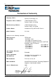
iv Declaration of Conformity Company Name: StorCase Technology, Inc.
v Federal Communications Commission (FCC) Statement RADIO FREQUENCY INTERFERENCE STATEMENT You are cautioned that changes or modifications not expressly approved by the party responsible for compliance could void your authority to operate that equipment. This device complies with part 15 of the FCC rules.
vi Table of Contents INTRODUCTION ..................................................................................................................... Packaging Information ...................................................................................................... Serial Number ................................................................................................................ General Description .......................................................................................
vii Edit Menu/Toolbar ....................................................................................................... Command Buttons ....................................................................................................... Configuring Volumes .......................................................................................................... Advanced Configuration ................................................................................................ Wizard ...........
viii List of Figures Figure 1: Figure 2: Figure 3: InfoStation 5-Bay SATA 3Gbps RAID Chassis ............................................. 3 InfoStation Front Panel ................................................................................... 5 InfoStation Rear Panel .................................................................................... 7 Figure Figure Figure Figure Controller Module Panel ..................................................................................
ix Figure A-1: InfoStation 5-Bay Physical Dimensions ...................................................... 53 Figure Figure Figure Figure Figure Power Supply Module .................................................................................. Fan Module ................................................................................................... Drive Carrier ................................................................................................. Rack Mount Conversion Kit ..........
Introduction 1 INTRODUCTION Packaging Information The StorCase Technology InfoStation external expansion chassis is shipped in a container designed to provide protection and prevent damage during shipment, as confirmed by the International Safe Transit Association (ISTA Procedure 1A). The InfoStation was carefully inspected before and during the packing procedure at the factory. Evidence of any damage to the InfoStation should be reported to the shipper immediately.
2 Introduction General Description CAUTION: The InfoStation contains NO USER SERVICEABLE parts inside the unit. Refer ALL servicing to qualified service personnel! NOTES: The installation, configuration, and use of the StorCase InfoStation chassis requires a certain level of expertise and experience on the part of the user/ integrator. Since there are many configuration options and variables (ie.
Introduction 3 Features: • • • • • • • • • • • • • • • • • Provides one (1) SATA 3Gbps host connection with 3/1.5Gbps auto-negotiation Five (5) removable low-profile drive carriers for 3.
4 Introduction Front Panel (Figure 2) • SCA Drive Carrier(s) - Accommodate up to five (5) 3.5" SATA 3Gbps devices. Backplane design with direct-connect SCA connectors eliminates cable connections to SATAII drives, increases data integrity, and supports drive hot swappability. • Drive Bay LED(s) - Provide the following information: • Drive Ready (BLUE) Indicates that the drive is properly installed and ready for access. Drive Activity (YELLOW) Indicates that the drive is being accessed.
Introduction 5 Removable Drive Carrier Drive Bay LEDs Chassis LEDs Fan Fault Rebuild OverTemp System Fault Power Figure 2: InfoStation Front Panel InfoStation 5-Bay RAID User's Guide - Rev. C00 StorCase Technology, Inc.
6 Introduction Rear Panel (Figure 3) WARNING: • DO NOT USE MODULE HANDLES TO LIFT CHASSIS! These handles are specifically designed for the installation and removal of modules only! Controller Module - Provides one (1) connector for SATA 3Gbps host connection. 3/1.5 Gbps auto-negotiation. Refer to section "Controller Module Panel" for further information. • Power Supply Module - One (1) 300W power supply module (features overvoltage and overcurrent protection, and power supply fault detection).
Introduction 7 Controller Module SATA 3Gbps Connector Cooling Fan Reserved (For Service Only) Power Supply Module A/C Power In Power Switch Figure 3: InfoStation Rear Panel InfoStation 5-Bay RAID User's Guide - Rev. C00 StorCase Technology, Inc.
8 Controller Module CONTROLLER MODULE PANEL SATA 3Gbps Port SERIAL e ATA 3 Gb/s FOR SERVICE ONLY Reserved Port RESET Reset Switch Figure 4: Controller Module Panel Panel Components SATA Port - eSATA connector used for SATA 3Gbps host. 3/1.5 Gbps autonegotiation. Reserved Port - Reserved for factory use. Reset Switch - Resets InfoStation UI (will not reset SATA Bus). StorCase Technology, Inc. InfoStation 5-Bay RAID User's Guide - Rev.
Controller Module 9 Inserting a Drive Carrier (with Drive Installed) NOTE: A new drive can be inserted into an empty bay at anytime. However, the drive will not be ready for access until the following procedure is followed. 1. Simply insert the drive carrier into the empty bay. Push handle in to lock carrier into place. 2. Drive is ready to be accessed when the Drive Ready LED glows BLUE.
10 Installation INSTALLATION CAUTION: The InfoStation contains NO USER SERVICEABLE PARTS inside the unit. Warranty is VOID if any of the modules inside the InfoStation are opened. Refer ALL servicing to qualified service personnel! NOTE: Before removing any component from its packaging, discharge any static electricity by touching a properly grounded metal object. While performing the steps in this section, work on a soft surface to prevent excessive shock to the drive(s) being installed.
Installation 11 Drive Preparation 1. Remove the drive from its protective packaging. Carrier Preparation The InfoStation is shipped in a container designed to provide protection and prevent damage during shipment, as confirmed by the International Safe Transit Association (ISTA Procedure 1A). The drive carriers are individually packed in a special foam insert within the InfoStation shipping carton. Simply remove them from the foam insert when ready for use.
12 Installation Removing/Installing the Power Supply Module WARNING: Handling certain plastic coated cords or cables associated with this product may expose you to lead, a chemical known to cause birth defects or other reproductive harm. Wash your hands after handling cable(s). CAUTION: The power supply module contains NO USER SERVICEABLE PARTS inside the unit. Warranty is VOID if module is opened. Refer ALL servicing to qualified service personnel! 1.
Installation 13 Installing the SATA Host Bus Adapter (HBA) CAUTION: The HBA contains NO USER SERVICEABLE PARTS inside the unit. Warranty is VOID if HBA is tampered with. Refer ALL servicing to qualified service personnel! Remove ALL power from the computer before installing the HBA. Before removing any component from its packaging, discharge any static electricity by touching a properly grounded metal object.
14 Installation HBA Driver Installation NOTES: HBA driver must be installed before installing the RAID Manager software. The SATA HBA driver is included on the StorCase Resource Kit CD (provided). Once the HBA has been installed onto the host computer, you will need to install the driver (provided). When Windows detects the newly installed HBA, the Driver Installation Wizard will prompt you for the location of the necessary driver. 1.
Installation 15 RAID Manager Installation NOTES: HBA driver must be installed before installing the RAID Manager software. The RAID Manager application is included on the StorCase Resource Kit CD (provided). MS Windows 1. Insert the StorCase Resource Kit CD into the host computer's CD-ROM drive. 2. Browse to the "IFS 5-Bay SATA 3Gbps" folder. Open the "Windows" folder. 3. Double-click the Setup.exe file. Follow the Installation Wizard to complete installation. 4.
16 Installation Mac OS X 1. Insert the StorCase Resource Kit CD into the host computer's CD-ROM drive. 2. Browse to the "IFS 5-Bay SATA 3Gbps" folder. Open the "Mac" folder. 3. Double-click the SiI_4726_Manager_V4.0.0.9.pkg file. Click Continue to dismiss the start screen. 4. Read the release-specific Read Me and click Continue. 5. Read the software license agreement and click Continue. Click Agree to accept agreement. 6. Select the local hard drive and click Continue. 7. Click Install.
Installation 17 Initialization/Partitioning of Drives Once all the drives have been installed and the InfoStation has been connected to the host computer, you will need to initialize or partition the drives through your OS Device Manager. MS Windows NOTE: Do not initialize or partition the sixth drive! 1. Right-click the My Computer icon on your desktop and select Manage from the pop-up menu. 2. Click Disk Management under Storage to view the drives. 3.
18 Installation Mac OS X NOTES: Do not initialize or partition the sixth drive (labeled as "320.0KB Config Disk Media")! A warning message will appear everytime the Mac system is rebooted. Ignore this message. 1. A warning will appear upon reboot of the Mac system. Mac OS X does not identify a recognizable file system. Click Ignore as many times as needed to dismiss all the error message boxes. 2. Launch Disk Utility from the Application > Utilities folder to view the drives. 3.
Installation 19 TYPICAL SATA CONFIGURATIONS NOTES: The installation, configuration, and use of the StorCase InfoStation chassis requires a certain level of expertise and experience on the part of the user/ integrator. Since there are many configuration options and variables (ie. host platforms, applications, etc), only general/typical configuration guidelines will be discussed in this User's Guide.
20 NOTES: Installation The InfoStation 5-Bay HBA has four (4) SATA ports, each designed to operate independently of each other via the RAID Manager software. When connecting multiple InfoStation 5-Bay enclosures to the same HBA, each enclosure must be configured and maintained individually.
RAID Configuration 21 RAID BASICS NOTES: The configuration and use of RAID requires a certain level of expertise and experience on the part of the user/integrator. Since there are many configuration options and variables (i.e.. host platforms, applications, etc.), only general guidelines will be discussed in this User's Guide. Also refer to the disk manufacturer's documentation for specific information regarding the disks.
22 RAID Configuration Comparing RAID Levels Table 1 illustrates the differences between the various RAID levels.
RAID Configuration 23 Storage Policies The following terms represent the InfoStation 5-Bay configuration options (storage policies), for mapping physical to virtual drives. The user can choose from these policies when configuring volumes (virtual drives) using the Basic Configuration Wizard or the Advanced Configuration Wizard. JBOD Grants the host computer direct access to physical drive(s). The number of available virtual drives is equal to the number of physical drives.
24 RAID Configuration Hot Spare One or more drives are unused during normal operation and are configured to be a spare. If an active drive in a SAFE volume fails, the data on the remaining drive is duplicated onto the Hot Spare to regain redundancy. All SAFE volumes can have a designated Hot Spare. Volume A virtual drive comprised of one or more physical drives. Once the user creates a volume, the OS uses and maintains the volume as if it were a single drive.
RAID Configuration 25 GETTING STARTED MS Windows 1. Select Start > Programs > InfoStation Manager icon to start the RAID Manager. Mac OS X 1. Launch the Finder and locate the InfoStation RAID program within the Applications > Utilities > InfoStation RAID folder. Click the InfoStation icon to start the RAID Manager. 2. If the launch sequence does not find an active Daemon, a warning will appear. Click OK. 3. Enter the administrator password (default= admin). Click OK. 4.
26 RAID Configuration RAID MANAGEMENT NOTES: The configuration and use of RAID requires a certain level of expertise and experience on the part of the user/integrator. Since there are many configuration options and variables (i.e.. host platforms, applications, etc.), only general guidelines will be discussed in this User's Guide. Also refer to the disk manufacturer's documentation for specific information regarding the disks.
RAID Configuration 27 Toolbar System Status Drive Status Capacity Information Figure 9B: Status Screen Components (Actual screen may vary) STATUS CELLS System Status Not Applicable Drive Status • Box Status Shows the drive status: Normal, Rebuilding, Unplugged, Needs Rebuild, New Drive, Wrong Slot. • Drive S/N Shows the unique serial number assigned by the drive manufacturer. • Exp. S/N Shows the expected serial number of the drive.
28 RAID Configuration • Total Shows the combined capacity of the volume. • Drive # Shows the capacity information for each drive. • Capacity Shows the full amount of storage space (in GB) available for each drive. • Volume Shows the total volume capacity and the drive capacities assigned to each volume. FILE MENU • Change Password Allows user to change password (default = admin). • Scan Devices Allows user to refresh status details displayed in Status Window.
RAID Configuration 29 Basic Configuration The Basic Configuration Wizard (Figure 10) is accessed from the Status Window and allows the user to manage volume. Volumes are based on a user-selected storage policy. User cannot modify volume counts or capacities. To protect against unauthorized changes, the RAID GUI Manager will prompt for a password when accessing the Wizard for the first time.
30 RAID Configuration EDIT MENU/TOOLBAR • Read Reads a saved configuration so that the user can apply the configuration to the InfoStation. • Write Saves a configuration to a file on the host computer. • Restore Cancels proposed changes. COMMAND BUTTONS • To Advanced Mode Opens the Advanced Configuration Wizard. • Apply Submits configuration changes to the InfoStation and closes the Configuration Wizard. • Cancel Cancels proposed changes and closes the Configuration Wizard.
RAID Configuration 31 Configuring Volumes NOTE: Use the Disk Management utility (provided by the OS) to delete all partitions, except the unallocated, uninitialized drive that represents the InfoStation RAID processor. Refer to section "Partitioning Configured Volumes" for further information. The Basic Configuration Wizard (Figure 10) is accessed from the Status Window and allows the user to manage volume. Volumes are based on a user-selected storage policy.
32 RAID Configuration Advanced Configuration The Basic Configuration Wizard provides six (6) predefined storage policies (page 23) to quickly configure the InfoStation. Each predefined policy allocates the maximum system capacity to the selected policy. The Advanced Configuration Wizard (Figure 12) however, allows the user to configure up to ten (10) volumes, each with different storage policies and capacities.
RAID Configuration 33 • Drive Graph Displays disk space for each drive. All space allocated to the same volume appears in matching color. Hatch pattern indicates a proposed configuration, while a solid block indicates existing volume. • Advanced Controls Allows volume creation and modification to each drive: Hot Spare checkbox indicates space on this drive is allocated as rebuild space for the selected SAFE volume. Use checkbox indicates drive membership within a volume.
34 RAID Configuration COMMAND BUTTONS • To Basic Mode Opens the Basic Configuration Wizard. When configuring a volume (create a new volume or edit a selected volume) • Update Volume Applies the selected storage policy to a specific portion of a drive as a proposed configuration. • Cancel Cancels proposed changes and returns the Configuration Wizard to the point where the user can perform different advanced configuration functions.
RAID Configuration 35 Configuring Multiple Volumes NOTES: Use the Disk Management utility (provided by the OS) to delete all partitions, except the unallocated, uninitialized drive that represents the InfoStation RAID processor. Refer to section "Partitioning Configured Volumes" for further information. Only the last volume listed can be edited. In order to edit volume 1, volume 2 must be deleted. In order to edit volume 0, all volumes must be deleted (user will need to start with a new volume).
36 RAID Configuration Managing Configuration Files NOTE: The user must have previously saved a configuration file so that one is available to import. Refer to section "Save a Configuration File" for further information. The Basic Configuration Wizard (File menu) allows the user to manage configuration files. • Read Config File Imports a configuration file so that the user can restore a previously saved configuration (storage policy).
RAID Configuration 37 Partitioning Configured Volumes The user must partition volumes for the host computer's OS before usage. Refer to the OS manufacturer's documentation for further information. Partitioning a Volume MS Windows NOTE: Before reconfiguring a volume, backup the data and delete previously defined InfoStation partitions. However, DO NOT delete the partition that represents the InfoStation RAID processor (the "Not Initialized" drive with no capacity allocated).
38 RAID Configuration Mac OS X NOTE: Before reconfiguring a volume, backup the data and delete previously defined InfoStation partitions. However, DO NOT delete the partition that represents the InfoStation RAID processor (the "Not Initialized" drive with no capacity allocated). User can then restore backed-up data to the new configuration once new volumes are configured and partitioned. 1. Launch Disk Utility from Application > Utilities folder. 2.
RAID Configuration 39 ADMINISTRATION Changing the Password The password information is stored locally on the server running the daemon. password= admin. 1. Select Change Password from the File menu. 2. Enter the current password (default = admin). 3. Enter the new password (5 characters minimum) in both fields. 4. Click OK to implement new password.
40 RAID Configuration Setting Up a Remote Connection 1. Select Change Connection from the File menu in the Status window. 2. Enter the host name or IP address of the PC hosting the Daemon. Click OK. The User Interface will establish the requested connection and will display the information gathered by the Remote Daemon in the Status window. StorCase Technology, Inc. InfoStation 5-Bay RAID User's Guide - Rev.
RAID Configuration 41 Configuring SAFE Volume Rebuild Storage Policy NOTE: The rebuild feature also applies to other SAFE policies, such as SAFE and BIG and SAFE and FAST. When is a rebuild necessary? A rebuild is initiated to restore data redundancy for a SAFE volume entering a vulnerable state. In a vulnerable state, one of the two mirrored drives goes offline or is inaccessible.
42 RAID Configuration Figure 13: Policy Specification 2. 3. 4.
RAID Configuration 43 EMAIL NOTIFICATION This feature allows the InfoStation to send an email if any of the following conditions occur: • • • • • • Partition Rebuild Start Partition Verify Start Partition Rebuild Resume System Fan Too Slow No Boxes Found Drive Unplugged • • • • • • Partition Rebuild Complete Partition Verify Complete Temperature Too High Power Supply Fan Too Slow Box Removed Drive Inserted Each of the above conditions can be customized for sending options as well as the message that i
44 RAID Configuration Setting Up Email Notification 1. Do not enter anything in the SMTP Server Name field (leave blank). The InfoStation RAID Manager will perform a DNS lookup and automatically assign the correct address. 2. If blank, enter 25 in the SMTP Server Port # field (default = Port 25). 3. Enter the intended recipients' email addresses in the To: and CC: fields. In the From: field, user should enter his/her own email address.
RAID Configuration 45 MONITORING This section describes Status window code colors, LED indicator status, and event log messages used to troubleshoot the InfoStation. Monitoring Drive Status The color of the drives in the Status window indicates the status of the drives. Color State Definition Resolution Green Normal Drive is active. N/A Red Needs rebuild Drive has failed. Replace the failed drive. Gray or Red Unplugged Drive is offline. Background will turn red after a write to the volume.
46 RAID Configuration Reviewing Event Logs Event logs are useful for troubleshooting and locating a system malfunction. 1. Select Event Log from the Edit menu of the Status window. Figure 15: Event Log 2. The Event Log will display a list of events in a table format. Date column displays the date and time of the event. Box SN and Drive SN columns display the respective serial numbers for the event. Drive Manufacturer column displays vendor information. Message column displays event description. 3.
RAID Configuration 47 TROUBLESHOOTING Problem Resolution InfoStation not recognized by HBA BIOS Verify power to chassis. Verify eSATA connection. If necessary, try an alternate eSATA cable. Verify that HBA BIOS recognizes empty InfoStation. Turn off PCI bus power save mode in the host BIOS. Troubleshooting the HBA: • Connect to an alternate SATA port. • Connect an alternate device to the HBA. • Remove all other PCI peripherals to rule out interference. • Move the HBA to an alternate PCI-X slot.
48 RAID Configuration (cont'd) Problem Resolution OS not recognizing one or more InfoStation volumes Identify maximum SATA drive capacity supported by the OS and ensure volume size meets limits. Verify port multiplier support in the HBA. StorCase Technology, Inc. InfoStation 5-Bay RAID User's Guide - Rev.
Appendix A - Specifications/Dimensions 49 APPENDICES InfoStation 5-Bay RAID User's Guide - Rev. C00 StorCase Technology, Inc.
50 Appendix A - Specifications/Dimensions Appendix A - Specifications/Dimensions The following InfoStation specifications and dimensions are provided for reference only.
Appendix A - Specifications/Dimensions 51 StorCase InfoStation P/N SATA 3Gbps RAID Enclosure S11J104 # of Drives Supported 5 # of Drive Carriers Included 5 Max. # of Drives Supported 5 Max. Storage Capacity: (Based on 400GB SATA Drives) 1.6TB (unformatted) Hot Swappable Carriers LED Status Indicators Yes Yes Host Interface: SATA Transfer Rate Connector Type Disk Interface: Transfer Rate 1 Channel 3Gbps eSATA SATA 3Gbps/1.
52 Appendix A - Specifications/Dimensions StorCase InfoStation P/N SATA 3Gbps RAID Enclosure S11J104 RAID Features RAID Level Support: Max. Devices Supported: Max. # of Arrays JBOD, 0, 1, and 10 5 8 (per HBA Channel) Dedicated/Global Spare Supported: Yes PCI Interface: Number of Channels: Supported OS: PCI-X, 133 MHz, 64-bit 4 Windows XP, 2000/2003 Professional Edition Windows 2000/2003 Server Edition Mac OS X HBA Compliance SATA 3Gbps Port Multiplier Rev. 1.2 SATA Specification Rev. 1.
Appendix A - Specifications/Dimensions 53 Top View Front View Right Side View 8.70 (221.0mm) 5.14 (130.6mm) 11.87 (301.5mm) Figure A-1: InfoStation 5-Bay Physical Dimensions (Dimensions are for reference only) InfoStation 5-Bay RAID User's Guide - Rev. C00 StorCase Technology, Inc.
54 Appendix B - Optional Accessories Appendix B - Optional Accessories Replacement Power Supply Module CAUTION: The power supply module contains NO USER SERVICEABLE PARTS inside the unit. Warranty is VOID if module is opened. Refer ALL servicing to qualified service personnel! A replacement 300W power supply module (P/N S10A180) is available for the InfoStation chassis. Contact StorCase for further ordering information. Figure B-1: Power Supply Module StorCase Technology, Inc.
Appendix B - Optional Accessories 55 Replacement Fan Module CAUTION: The fan module contains NO USER SERVICEABLE PARTS inside the unit. Warranty is VOID if module is opened. Refer ALL servicing to qualified service personnel! A replacement fan module (P/N S11E100) is available for the InfoStation chassis. Contact StorCase for further ordering information. Figure B-2: Fan Module Drive Carrier Spare drive carriers (P/N S10J101) are available for the InfoStation chassis.
56 Appendix B - Optional Accessories Rack Mount Conversion Kit The optional rack mount conversion kit (P/N S11E101) is designed to convert two (2) InfoStation 5-Bays into a 3U rack mount. Contact your StorCase dealer for further details and ordering information.
Reader's Comments 57 Reader's Comments Please take a few moments when your computer system is up and running to send us your ideas and suggestions for improving our products and documentation.
Reader's Comments CUT ALONG THIS LINE FROM BOTTOM TO TOP OF PAGE 58 FOLD ALONG THIS LINE AND STAPLE SHUT NO POSTAGE NECESSARY IF MAILED IN THE UNITED STATES B U S I N E S S R E P LY M A I L FIRST CLASS MAIL PERMIT NO. 10686 SANTA ANA, CA POSTAGE WILL BE PAID BY ADDRESSEE TECHNOLOGY CORPORATION 17600 NEWHOPE STREET FOUNTAIN VALLEY CA 92708-9885 StorCase Technology, Inc. InfoStation 5-Bay RAID User's Guide - Rev.