
Instruction Manual

Controller Module 11
InfoStation 16-Bay RAID User's Guide - Rev. F00 StorCase Technology, Inc.
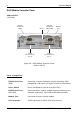
FC-to-SATA
(S10K112)
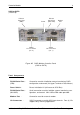
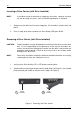
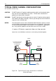
Figure 4D: RAID Module Controller Panel
(FC-to-SATA)
Modem
Port
RS-232
Serial Port
(DB9)
RS-232
Serial Port
(Mini USB)Reset
In
FC Ports
(Loop A)
Ready
LED
2Gbps
LED
Error
LEDs
Out In Out
FC Ports
(Loop B)
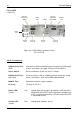
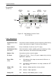
Panel Components
RS-232 Serial Port - Connection used for InfoStation external monitoring, RAID config-
(DB9) uration, and control (via Hyper Terminal or Data Master).
Reset Switch - Resets InfoStation UI (will not reset FC Loops).
RS-232 Serial Port - Serial connection used for InfoMon external monitoring, config-
(Mini USB) uration, and control. Mini USB-to-DB9 cable provided.
Modem Port - Connection used for external modem.
FC Ports - FC ports for FC-ALs. Four (4) FC ports support daisy-chaining
applications (optional).
Error LEDs - In = ON indicates either loop not connected, HBA error, or
(Red) cabling problem.
Out= ON indicates RAID Module is not ready (should turn OFF
after 15 sec).
2Gbps LED - ON = Indicates 2Gbps operation (factory default).
(Green)
OFF= Indicates 1Gbps operation.
Ready LED - ON= Indicates RAID Module power is ready.