StorCase® Technology InfoStation® 12-Bay SCSI-to-Serial ATA 12-Bay FC-to-Serial ATA RAID External Expansion Chassis Installation Guide
i StorCase® Technology InfoStation® 12-Bay SCSI-to-Serial ATA 12-Bay FC-to-Serial ATA RAID External Expansion Chassis Installation Guide Part No. D89-0000-0233 B00 October 2003 StorCase Technology, Inc. 17600 Newhope Street Fountain Valley, CA 92708-9885 Phone (714) 438-1850 Fax (714) 438-1847 InfoStation 12-Bay RAID Installation Guide - B00 StorCase Technology, Inc.
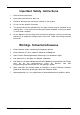
ii Important Safety Instructions 1. Read all these instructions. 2. Save these instructions for later use. 3. Follow all warnings and instructions marked on the product. 4. Do not use this product near water. 5. This product should be operated from the type of power source indicated on the marking label. If you are not sure of the type of power available, consult your dealer or local power company. 6.
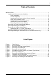
iii Table of Contents INSTALLATION ...................................................................................................................... 1 Installing the Drive(s) into the InfoStation ................................................................... 1 Drive Preparation .................................................................................................. 1 Carrier Preparation ...............................................................................................
iv NOTICE: This User's Guide is subject to periodic updates without notice. While reasonable efforts have been made to ensure accuracy of this document, StorCase Technology, Inc. assumes no liability resulting from errors or omissions in this publication, or from the use of the information contained herein. Please check the StorCase web site at http://www.storcase.com or contact your StorCase representative for the latest revision of this document. StorCase Technology, Inc.
Installation 1 INSTALLATION CAUTION: The InfoStation contains NO USER SERVICEABLE PARTS inside the unit. Warranty is VOID if any of the modules inside the InfoStation are opened. Refer ALL servicing to qualified service personnel! This unit has more than one power supply cord. Disconnect two power supply cords before servicing to avoid electric shock. Danger of explosion if the RAID battery is incorrectly replaced! Replace only with the same or equivalent type recommended by the manufacturer.
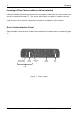
2 Installation Inserting a Drive Carrier (without a Drive Installed) Lift carrier handle while inserting drive carrier into chassis. Push down on carrier handle once carrier is pushed all the way in. The carrier should latch into place if inserted correctly. Lock the key lock to prevent unauthorized removal or installation of drive carrier. Drive Carrier Interface Panel Each InfoStation drive carrier provides a User interface for individual carrier operation (Figure 1).
Installation 3 Installing a Drive into the Drive Carrier NOTE: 1. A #2 Phillips screwdriver will be required for this procedure. Carefully insert the drive into the carrier. Slide the drive towards the Drive Carrier Board, so that the I/O connector on the drive mates with the connector on the Drive Carrier Board. Drive(s) must be bottom-mounted into the drive carrier(s) using four (4) Phillips Flat Hd. screws (Figure 2). NOTE: 2.
4 Installation Inserting a Drive into the Chassis NOTES: A new drive can be inserted into an empty bay at anytime. However, the drive will not be ready for access until the following procedure is followed. The key lock is only to prevent unauthorized removal or installation of the drive carrier. Locking the key lock is not required for drive carrier operation. 1. Drive is ready to be accessed when the Drive Ready LED glows.
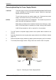
Installation 5 Removing/Installing the Power Supply Module CAUTION: The power supply module contains NO USER SERVICEABLE PARTS inside the unit. Warranty is VOID if module is opened. Refer ALL servicing to qualified service personnel! This unit has more than one power supply cord. Disconnect two power supply cords before servicing to avoid electric shock. NOTES: The power supply module is hot-swappable. The chassis may remain on when removing and installing the module.
6 Installation Removing/Installing the Fan Module CAUTION: The fan module contains NO USER SERVICEABLE PARTS inside the unit. Warranty is VOID if module is opened. Refer ALL servicing to qualified service personnel! This unit has more than one power supply cord. Disconnect two power supply cords before servicing to avoid electric shock. NOTES: The fan module is hot-swappable. The chassis may remain on when removing and installing the module.
Installation 7 Removing the Chassis Access Panel CAUTION: Remove ALL power from the InfoStation before removing the access panel(s). The InfoStation contains NO USER SERVICEABLE PARTS inside the unit. Warranty is VOID if any of the modules inside the InfoStation are opened. Refer ALL servicing to qualified service personnel! NOTE: A #2 Phillips screwdriver will be required for this procedure. 1. Unplug the InfoStation and verify that ALL cables have been disconnected. 2.
8 Installation Installing a Half-Height 5.25" SCSI Device (such as a Canister-Type Device) CAUTION: Remove ALL power from the InfoStation before removing the access panel(s). The InfoStation contains NO USER SERVICEABLE PARTS inside the unit. Warranty is VOID if any of the modules inside the InfoStation are opened. Refer ALL servicing to qualified service personnel! This unit has more than one power supply cord. Disconnect two power supply cords before servicing to avoid electric shock.
Installation 7. 9 Carefully remove the I/O Panel (located in the rear of the chassis) by loosening the two (2) Captive Screws (Figure 7). The attached cables will provide enough slack for the I/O Panel to be removed a few inches from the chassis. I/O Panel Captive Screw (2 Total) Figure 7: Removing the I/O Panel (SCSI-to-SATA version shown) 8. Once I/O panel is removed, loosen and remove the two (2) #6-32 Phiilips Flat Hd. screws securing the I/O Blank Plate to the I/O Panel (Figure 8).
10 Installation 9. Install the provided I/O Cut-Out Plate (Figure 9) onto your SCSI Cables. NOTES: The I/O Cut-Out Plate can be found inside the InfoStation accessory packet. SCSI cables are not included. Figure 9: InfoStation I/O Cut-Out Plate 10. Install the I/O Plate onto the I/O Panel using the same screws saved from Step 8. 11. Install cables onto the SCSI device and carefully reinstall the I/O Panel back onto the rear of the InfoStation chassis.
Installation 11 FC Cable Installation (For FC-to-SATA version only) CAUTION: DO NOT bend the LC (optical) cable beyond the cable's minimum bend radius, data transmission degradation may occur. Follow cable manufacturer's guidelines for bend radius limitation. WARNING: DO NOT look directly into the open end of an active LC (optical) cable or optical SFP module (with plugs removed)! Serious eye damage can occur from direct exposure to the infrared light! NOTES: SFP Module is hot-swappable.
12 Installation Removing/Installing the SFP Module (For FC-to-SATA version only) WARNING: DO NOT look directly into the open end of an active LC (optical) cable or optical SFP module (with plugs removed)! Serious eye damage can occur from direct exposure to the infrared light! NOTES: SFP Module is hot-swappable. The chassis may remain on when removing and installing the SFP Module. LC (optical) SFP Modules support both 2Gbps and 1Gbps operation.
Installation 13 To install SFP Module(s) into the FC Port, follow Step 3 below. 3. Carefully insert SFP Module(s) into the FC Port(s). Push the SFP Module until it 'clicks' into place (Figure 11). WARNING: To avoid possible damage to the SFP Module, make sure the Release Lever is on top before inserting SFP Module into the FC Port (Figure 11)! InfoStation 12-Bay RAID Installation Guide - B00 StorCase Technology, Inc.