
Owner's manual
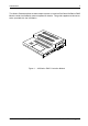

4 Introduction
StorCase Technology, Inc. S10C100 User's Guide - Rev. A01
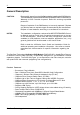
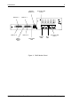
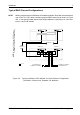
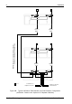
INFOSTATION RAID Module Panel
(Figure 2)
FC-AL/FC-SW Port A - HSSDC connectors (N+1 and N-1) provide a standard
interface for external FC devices. Connects to FC Host 0
FC-AL/FC-SW Port B - HSSDC connectors (N+1 and N-1) provide a standard
interface for external FC devices. Connects to FC Host 1.
Bypass LED - Provides the following information:
ON (Green) = Indicates that FC port is bypassed (disconnected from the
loop/switch)
OFF = Indicates that FC port is not bypassed
Error LED - Provides a visual indication of error conditions:
ON (Amber) = Indicates that there is an error detected from the external FC
host/device
OFF = Indicates that there are no errors
Disk Channels 0-3 - Each channel supports up to fifteen (15) Ultra160 (downward
compatible to Ultra2) disks maximum (60 disks total).
Diagnostic LED - Provides the following information:
ON = Indicates that RAID Controller Module PASSES diagnostic check
OFF = Indicates that RAID Controller Module FAILS diagnostic check
Cache Backup LED - Provides the following information:
ON = Indicates that data is in Cache Memory
OFF = Indicates that data write to disk is complete
RS-232 Serial Port (RAID Configuration Port) - Connects to a VT-100/ANSI terminal
via an RJ45-DB9 cable (provided). Refer to section "Configuration" for further
information.