StorCase® Technology Data Silo® DS550 Tower and Rack Mount 9-Bay External SCSI Expansion Chassis User's Guide
i StorCase® Technology Data Silo® DS550 Tower and Rack Mount 9-Bay External SCSI Expansion Chassis User's Guide Part No. D89-0000-0183 A04 January 2003 StorCase Technology, Inc. 17600 Newhope Street Fountain Valley, CA 92708-9885 Phone (714) 438-1850 Fax (714) 438-1847 DS550 User's Guide - Rev. A04 StorCase Technology, Inc.
ii LIMITED WARRANTY STORCASE TECHNOLOGY, Incorporated (StorCase) warrants that its products will be free from defects in material and workmanship, subject to the conditions and limitations set forth below. StorCase will, at its option, either repair or replace any part of its product that proves defective by reason of improper workmanship or materials.
iii Free Technical Support StorCase provides free technical support. If you experience any difficulty during the installation or subsequent use of a StorCase product, please contact StorCases Technical Support Department prior to servicing your system. This warranty covers only repair or replacement of defective StorCase products, as described above. StorCase is not liable for, and does not cover under warranty, any costs associated with servicing and/or installation of StorCase products.
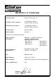
iv Declaration of Conformity Company Name: StorCase Technology, Inc.
v Important Safety Instructions 1. Read all these instructions. 2. Save these instructions for later use. 3. Follow all warnings and instructions marked on the product. 4. Do not use this product near water. 5. This product should be operated from the type of power source indicated on the marking label. If you are not sure of the type of power available, consult your dealer or local power company. 6.
vi Table of Contents INTRODUCTION ..................................................................................................................... Packaging Information .................................................................................................. Serial Number ................................................................................................................ General Description ...........................................................................................
vii List of Figures Figure 1: Figure 2: Figure 3: Figure 4: Figure 5: Figure 6: Figure 7: Figure 8: Figure 9: Figure 10: Figure 11: Figure 12: Figure 13: DS550 Rack Mount and Tower Models ........................................................ 2 DS550 Drive Installation Overview ............................................................... 3 DS550 Front Panel .......................................................................................... 4 DS550 Rear Panel ..................................
Introduction 1 INTRODUCTION Packaging Information The StorCase Technology Data Silo® external expansion chassis is shipped in a container designed to provide protection and prevent damage during shipment. The Data Silo was carefully inspected before and during the packing procedure at the factory. Evidence of any damage to the Data Silo should be reported to the shipper immediately.
2 Introduction General Description CAUTION: The DS550 contains NO USER SERVICEABLE parts inside the unit. Refer ALL servicing to qualified service personnel! WARNING: DO NOT ship/transport DS550 chassis with RAID battery installed! Battery may loosen during shipping which can result in fire and/or explosion! Danger of explosion if RAID battery is incorrectly installed! Install only with the same or equivalent type battery recommended by the manufacturer.
Introduction 3 550_7 DS550 Rack Mount DS550 Tower Figure 1: DS550 Rack Mount and Tower Models Installation Overview (Figure 2) This User's Guide describes the steps required for installing drive(s) into the Data Silo DS550 tower or rack mount external expansion chassis. For consistency, most illustrations depict the DS550 rack mount model. Although cosmetically different on the exterior, the tower and rack mount models are identical on the interior.
4 Introduction Side Cover Latch (2 plcs) Access Cover Screw (16 Total) Cable Access Cover (Top & Bottom) Power Cable Tab Right Cover Rear Panel I/O Panel Mounting Screw (2 per Panel) Side Cover Screw (2 plcs) Side Cover Removal (Tower Model) Adapter Bracket Mounting Screw (4 per Drive) 550_11 3.
Introduction 5 Front Panel (Figure 3) The front panel display contains seven (7) lights which provide the following information: Power-On - Steady green glow indicates that power is being supplied to the Data Silo chassis. Temperature Warning - Flashing red indicates that internal operating temperature has reached 43º C (109° F). Blower 1 or 2 Failure - Flashing red indicates a blower has failed. Power Supply 2 Failure - Flashing red indicates second power supply has failed.
6 Introduction Rear Panel (Figure 4) NOTE: If a module slot is to be left empty, the filler plate (provided) must be installed. Installation of the filler panel is necessary for proper cooling inside chassis. SCSI I/O Connectors - The DS550 chassis is unwired and comes equipped with rear panel cut-outs for up to six (6) I/Os. Power Supply Module(s) - Dual auto-ranging power supply modules run in Shared Mode which allows both to operate at reduced wattage and lower operating temperature.
Introduction 7 Factory-Reserved - Allows the installation of future StorCase upgrade products. Logic Card - Allows easy access to the DS550 hot-pluggable daughterboard (refer to Appendix B for further information).
8 Installation INSTALLATION CAUTION: The DS550 contains NO USER SERVICEABLE parts inside the unit. Refer ALL servicing to qualified service personnel! WARNING: DO NOT ship/transport DS550 chassis with RAID battery installed! Battery may loosen during shipping which can result in fire and/or explosion! Danger of explosion if RAID battery is incorrectly installed! Install only with the same or equivalent type battery recommended by the manufacturer.
Installation 9 Top Cover Screw Location (8 plcs) Bottom Cover Screw Location (8 plcs) A B C D 550_12 E F Figure 5: DS550 Rack Mount Cover Removal DS550 User's Guide - Rev. A04 StorCase Technology, Inc.
10 Installation 4. For Tower Models: Remove the side panels (Figure 6). Remove the side panel retaining screw as shown in Figure 6. Disengage the two (2) side panel latches on the side of the DS550. With the side panel partially open, lift the panel vertically to unhinge the tab (located at the bottom of the side panel) from the slots in the DS550 base. Remove the side panels. DS550 Base (Right Side) Front of DS550 DS550 Right Cover 550_13 Figure 6: StorCase Technology, Inc.
Installation 11 Drive Preparation 1. Remove the drive from its protective packaging. 2. Plastic Drive Bezel - If installing a hard drive which is equipped with a plastic front bezel, remove the drive bezel. 3. SCSI Drive Termination - The last drive on any SCSI channel must have termination enabled. In most instances, depending upon the cable configuration, termination will be handled by an external terminator on the DS550 back panel. If using an external terminator, disable onboard drive termination.
12 Installation 3.5 Drive (Not Included) S C 550_9 S II Adapter Bracket (Right Front) D N E W G IN N R A W Y R O T C FA Adapter Bracket (Left Front) the Fron Dri t of ve LE FT FR ON T #6-32 Phillips Pan Hd. Screw (4 Total) Figure 7: Attaching the 3.5" Adapter Bracket to the Drive Power Connector DS550 Power Strip Power Cable 550_14 Figure 8: Connecting the DC Power Cable to the Drive (Data Express® Removable Enclosure Shown) StorCase Technology, Inc. DS550 User's Guide - Rev.
Installation 13 Drive Installation 1. For fixed media devices: Install the drive activity and drive fault LEDs into the appropriate front filler panels. Gently push each LED into the rear of the filler panel (Figure 9). Flat Side of Connector Faces Up Device Filler Panel (back side) 0581 To 2mm Device Connector Figure 9: Installing the LEDs into the Filler Panel 2. For front-loading devices: Remove the appropriate filler panels from the DS550.
14 Installation 3. Attach the drive activity and drive fault indicator LED cables to the appropriate drive pins (refer to the device manufacturer's documentation for the location of these pins). 4. Install the drive(s) into the drive mounting bracket using four (4) #6-32 Phillips Pan Hd. screws (Figure 11). Be careful not to pinch or crimp attached cables. Do not fully tighten the screws at this point.
Installation 15 Typical DS550 Configuration If the DS550 is the last SCSI device on the SCSI bus, it will require the appropriate termination for the I/O connector. Refer to Figure 12 below for a typical dual SCSI host connection. Follow the directions that came with your computer system for cabling an external SCSI device to that system. To Host #1 To Host #2 Disk Ch. 2 (4 Disks) Disk Ch. 1 (5 Disks) DS550 #1 550_22 Disk Ch. 1 (5 Disks) Disk Ch.
16 Installation This Page Left Blank Intentionally. StorCase Technology, Inc. DS550 User's Guide - Rev.
Appendix A - Specifications/Dimensions 17 APPENDICES DS550 User's Guide - Rev. A04 StorCase Technology, Inc.
18 Appendix A - Specifications/Dimensions Appendix A - Specifications/Dimensions Environmental Specifications -40 C to 70 C 10% to 90% -1000 to 40,000 ft -305m to 12195m 0 C to 35 C 10% to 80% -1000 to 10,000 ft -305m to 3048m 10g Non-condensing with maximum gradient of 10% per hour. 11 msec pulse width 1/2 sine wave. Weight 6.98 (177.3mm) 20.70 (525.8mm) 19.00 (482.6mm) 10.98 (278.9mm) 23.87 (606.3mm) 23.21 (589.5mm) 54.5lbs (24.8kg) 70.5lbs (32.
Appendix A - Specifications/Dimensions 19 Figure A-1: DS550 Tower Physical Dimensions (Dimensions are for reference only) 16.92 (429.8mm) 4.58 (116.3mm) 15.36 (390.1mm) 13.04 (331.2mm) 0.20 (5.1mm) 2.62 (66.5mm) 23.87 (606.3mm) 8.06 (204.7mm) Top View 1.17 (29.7mm) 19.00 (482.6mm) Right Side View 6.98 (177.3mm) 1.75 (44.5mm) Front View 1.66 (42.2mm) 6.00 4.25 7.75 (152.4mm) (108.0mm) (196.
20 Appendix B - Optional Accessories Appendix B - Optional Accessories Internal SCSI Cables For a complete and current listing of StorCase external cable, power cable, and terminator options that can be used with this product, please visit the StorCase web site at www.storcase.com.
Appendix B - Optional Accessories 21 Figure B-1: SCSI Ultra160 Cable Kit (DCULTRA160-9KIT shown) DS550 User's Guide - Rev. A04 StorCase Technology, Inc.
22 Appendix B - Optional Accessories 9-Drive LVD Cable Kit The DCREMLVD-KIT, an internal cable kit designed for the StorCase 9-bay Data Silo rack mount or tower chassis, allows the DS550 to be used for SCSI Ultra160 applications implementing specific models of the Data Express removable drive enclosure. Contact StorCase for further information. The DCREMLVD-KIT (Figure B-2) consists of an internal 9-drive ribbon cable, LVD/S.E. terminator, and a VHDCI rear panel adapter plate.
Appendix B - Optional Accessories 23 RAID Cable Kit The DCW4RAID-KIT, an internal cable kit for the StorCase 9-bay Data Silo rack or tower chassis, allows the DS550 to be used with SCSI RAID configurations where the RAID controller resides within the Data Silo. The DCW4RAID-KIT includes two (2) drive channel cables, each with five (5) device connectors and an inline LVD/S.E. terminator, and one (1) host channel cable for connecting to the rear panel of the Data Silo (Figure B-3).
24 Appendix B - Optional Accessories SAF-TE Processor Board Kit The DS550 SAF-TE Processor Board Kit (P/N S30A110) is an optional upgrade for the DS550 chassis Figure B-4). Contact StorCase for further ordering information. Features include: - Monitors status of blowers and power supply modules Monitors chassis temperature Dedicated user-selectable SCSI ID Supports multi-mode (LVD/S.E.
Appendix B - Optional Accessories 25 Rack Mount-to-Tower Conversion Kit This kit provides all the parts necessary to convert an existing rack mount DS550 to a tower configuration, as shown in Figure B-5. The kit is available in a StorCase White finish (P/N DXTWR-KIT) and a black finish (P/N DXTWR-KIT/B). Contact StorCase for further ordering information. Figure B-5: DS550 Rack-To-Tower Conversion Kit DS550 User's Guide - Rev. A04 StorCase Technology, Inc.
26 Appendix B - Optional Accessories Tower-to-Rack Mount Conversion The DS550 tower model is shipped with two (2) handles and mounting screws located inside a plastic bag in the top of the chassis. These handles are provided so that the tower model may be converted to a rack mount configuration. To convert a tower model to a rack mount, remove the tower parts shown in Figure B-5 and attach the two handles to the DS550 chassis with two (2) screws each as shown in Figure B-6.
Appendix B - Optional Accessories 27 Slide Rail Kit The optional slide rail kit (P/N DXRCK-SLIDE) provides a convenient method to attach the DS550 to a rack mount enclosure (Figure B-7). The StorCase high quality, durable rails provide 24 ball bearing rollers and have a quick release button which allows quick and easy installation and removal of the DS550 unit from its rack enclosure. Contact StorCase for further ordering information.
28 Appendix B - Optional Accessories 3.5" Drive Adapter Brackets The DS550 comes standard with nine (9) 3.5" drive adapter brackets (Figure B-8) for mounting nine (9) fixed half-height or low-profile drives into the DS550 chassis. StorCase offers additional brackets as an option for mounting up to twelve (12) fixed low-profile drives. Contact StorCase for further ordering information. 3.
Appendix B - Optional Accessories 29 Replacing a Power Supply Module The DS550 comes equipped with two (2) auto-ranging power supply modules. This allows the DS550 chassis to run in Shared Mode, thus enabling both power supplies to operate at a reduced wattage and lower operating temperature. If one power supply module should fail, the other will carry the full load without interruption. Should a blower slow down or fail, a red indicator light on the front panel will flash.
30 Appendix B - Optional Accessories If module slot is to be left empty: The filler plate (provided) must be installed. Installation of the filler panel is necessary for proper cooling inside chassis. The Power Supply/Blower Error Logic must also be permanently disabled as described below.
Appendix C - DS550 Motherboard Connectors 31 Appendix C - DS550 Motherboard Connectors JA1 BCHAS RESERVED TTL Signals Header BFAN RESERVED BPS RESERVED HIGH TEMP RESERVED BCHAS BFAN BPS HIGH TEMP RESERVED RESERVED 5V GND 5V GND = Bad Chassis = Bad Fan = Bad Power Supply = High Temperature 6 5 4 3 2 1 JC1 3 2 = Pin 1 JB1 1 I2C Connector Pin 1 = SCL Pin 2 = SDA Pin 3 = INTR Pin 4 = GND Pin 5 = NC Pin 6 = NC Battery Connector Pin 1 = BATT CHRG Pin 2 = BATT GND Pin 3 = BATT DISCHRG DS
32 Appendix C - DS550 Motherboard Connectors This Page Left Blank Intentionally. StorCase Technology, Inc. DS550 User's Guide - Rev.
Reader's Comments 33 Reader's Comments Please take a few moments when your computer system is up and running to send us your ideas and suggestions for improving our products and documentation.
Reader's Comments CUT ALONG THIS LINE FROM BOTTOM TO TOP OF PAGE 34 FOLD ALONG THIS LINE AND STAPLE SHUT NO POSTAGE NECESSARY IF MAILED IN THE UNITED STATES B U S I N E S S R E P LY M A I L FIRST CLASS MAIL PERMIT NO. 10686 SANTA ANA, CA POSTAGE WILL BE PAID BY ADDRESSEE TECHNOLOGY CORPORATION 17600 NEWHOPE STREET FOUNTAIN VALLEY CA 92708-9885 StorCase Technology, Inc. DS550 User's Guide - Rev.