
Instruction Manual

D89-0000-0187 Rev. A04 StorCase Technology, Inc.
S30A110 7
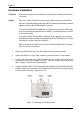
Hardware Installation
CAUTION: Remove ALL power from the DS550 and verify that ALL cables have been dis-
connected.
NOTES: Only one (1) SAF-TE Board is required per DS550 chassis (per SCSI Bus).
Up to two (2) DS550 chassis (each with SAF-TE installed) can be daisy-chained
together (optional DCULTRA160-9KIT required).
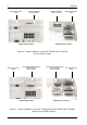
The optional I/O Board is available as an upgrade (your particular DS550 may
or may not already be equipped with I/O Board). Contact StorCase for further
ordering information.
The optional DCULTRA160-9KIT is available as an upgrade (your particular
DS550 may or may not already be equipped with DCULTRA160-9KIT). Contact
StorCase for further ordering information.
Refer to the Data Silo DS550 Users Guide and DCULTRA160-9KIT documen-
tation for further information.
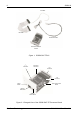
1. Unplug the DS550 and verify that ALL cables have been disconnected.
2. Place the DS550 on a soft, clean surface to protect the finish of the chassis.
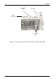
3. Loosen and remove the two (2) #6-32 Phillips Flat Hd. screws securing each I/O
blank plate to the DS550 chassis (Figure 3). Save the screws, they will be used
later in Step 4. Remove the I/O blank plates.
4. Carefully install the SAF-TE Processor Board and I/O Board [or DCULTRA160-9KIT
Repeater Board (not included)] into the empty I/O slots and secure using the same
screws saved from Step 3 (Figures 4 & 5).
Figure 3: Removing the I/O Blank Plate
Remove
Screws
I/O Blank
Plate
I/O Blank
Plate
DS550 Chassis (Rear)
550_26