S30A110 1 StorCase® Technology Data Silo® DS550 SAF-TE Kit (P/N S30A110) User's Guide Part No. D89-0000-0187 A04 March 2004 StorCase Technology, Inc. 17600 Newhope Street Fountain Valley, CA 92708-9885 Phone (714) 438-1850 Fax (714) 438-1847 D89-0000-0187 Rev. A04 StorCase Technology, Inc.
S30A110 LIMITED WARRANTY STORCASE TECHNOLOGY, Incorporated (StorCase) warrants that its products will be free from defects in material and workmanship, subject to the conditions and limitations set forth below. StorCase will, at its option, either repair or replace any part of its product that proves defective by reason of improper workmanship or materials.
S30A110 3 Declaration of Conformity Company Name: StorCase Technology, Inc.
S30A110 Table of Contents Data Silo DS550 SAF-TE Processor Board ........................................................................... 5 System Requirements ................................................................................................... 5 Hardware Installation ............................................................................................................... 7 SAF-TE Board with I/O Board Configuration ................................................................
S30A110 5 Data Silo® DS550 SAF-TE Processor Board The StorCase® Technology SAF-TE Processor Board (P/N S30A110) is an optional upgrade for the Data Silo DS550 enclosure, which is easily installed into the DS550 rear panel. Features include: - Monitors status of each DS550 blower and power supply module Monitors chassis temperature Dedicated, user-selectable SCSI ID Supports multi-mode (LVD/S.E.
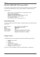
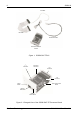
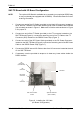
S30A110 I 2 C Cable I/O Cable 550_35 DC Power Cable SAF-TE Processor Board Figure 1: DS550 SAF-TE Kit I2C Connector DC Power Connector I/O Connector I/O Connector 550_27 Reset Switch SAF-TE Processor Board RS-232 Serial Port SCSI ID Select Switch Figure 2: Enlarged View of the DS550 SAF-TE Processor Board StorCase Technology, Inc. D89-0000-0187 Rev.
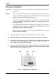
S30A110 7 Hardware Installation CAUTION: Remove ALL power from the DS550 and verify that ALL cables have been disconnected. NOTES: Only one (1) SAF-TE Board is required per DS550 chassis (per SCSI Bus). Up to two (2) DS550 chassis (each with SAF-TE installed) can be daisy-chained together (optional DCULTRA160-9KIT required). The optional I/O Board is available as an upgrade (your particular DS550 may or may not already be equipped with I/O Board). Contact StorCase for further ordering information.
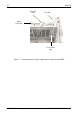
S30A110 SAF-TE Processor Board Optional I/O Board (Not Included) Optional I/O Board (Not Included) SAF-TE Processor Board 550_28 DS550 Chassis (Rear) DS550 Chassis (Interior) Figure 4: Typical Installation of the SAF-TE Board and I/O Board into the DS550 Chassis SAF-TE Processor Board Optional DCULTRA160-9KIT Repeater Board (Not Included) DS550 Chassis (Rear) Optional DCULTRA160-9KIT Repeater Board (Not Included) SAF-TE Processor Board DS550 Chassis (Interior) 550_30 Figure 5: Typical Inst
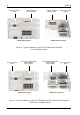
S30A110 9 SAF-TE Board with I/O Board Configuration NOTE: The optional I/O Board is available as an upgrade (your particular DS550 may or may not already be equipped with I/O Board). Contact StorCase for further ordering information. 1. Connect one end of the I/O Cable (provided) to the black I/O connector located on top of the SAF-TE Board; connect the remaining end of the I/O Cable to the I/O Board (not included) as shown in Figure 6. Make sure to fold the cable as shown in Figure 6 for proper fit.
S30A110 DC Power Cable I 2 C Cable DS550 Power Strip 550_29 I 2 C Connector (JB1) Figure 7: Connecting the DC Power Cable and I2C Cable to the DS550 StorCase Technology, Inc. D89-0000-0187 Rev.
S30A110 11 SAF-TE Board with DCULTRA160-9KIT Configuration NOTES: The optional DCULTRA160-9KIT is available as an upgrade (your particular DS550 may or may not already be equipped with DCULTRA160-9KIT). Contact StorCase for further ordering information. Refer to the DCULTRA160-9KIT documentation for further information. 1.
Device 3 of Device 4 Device 5 Device 6 Device 7 Device 8 Device 9 de Si nt 550 o Fr DS Device 1 S30A110 Device 2 12 I/O Cable DS DS550 Internal I/O Cable 0 55 Re ar 550_36 SAF-TE Board DCULTRA160-9KIT Repeater Board (Not Included) Figure 9: Typical Internal Cable Connection for the SAF-TE Board/DCULTRA160-9KIT Configuration StorCase Technology, Inc. D89-0000-0187 Rev.
S30A110 13 SAF-TE Board Front Panel (Figure 10) Reset Switch Resets the SAF-TE processor Board (resetting the SAF-TE Board is required if SCSI ID has been changed). RS-232 Serial Port Reserved. SCSI ID Select Switch Provides convenient SCSI ID selection. The rotating switch can be adjusted with the provided alignment tool (refer to section Selecting the SCSI ID Number for further information).
S30A110 SAF-TE Board SCSI ID Set-Up NOTES: SAF-TE board SCSI ID is factory set to SCSI ID15. The SAF-TE SCSI ID can be changed anytime. It will only take effect after resetting the SAF-TE Board (refer to section SAF-TE Board Front Panel for further information) and powering the Host OFF/ON. 550_34 Figure 11: Changing the SAF-TE Board SCSI ID StorCase Technology, Inc. D89-0000-0187 Rev.
S30A110 15 Software Installation NOTES: To install and operate the SAFTEmon® software, the computer system must meet certain system requirements (refer to page 5 of this document for further information). An IP address is required for remote monitoring via the internet. Please contact your system administrator to set up an IP address for the DS550 and host system. SAFTEmon is user-customizable.
S30A110 Figure 12: SAFTEmon.exe Window NOTE: The SAFTEmon.exe window will only appear on the host system. It cannot be viewed by remote monitoring via the internet (only the HTML files within the SAFTEmon.exe window are viewable via the internet). SAFTEmon is comprised of three (3) HTML files: SAFTEmon Main Configuration SCSI Information To view any of these HTML files on the host system, double-click on any of the file names within the SAFTEmon.exe window.
S30A110 17 Main Status Screen NOTE: When remote monitoring via the internet, always hit "Refresh" on the browser to make sure you are viewing the most up-to-date information. The Main Status Screen (Figure 11) displays the following "at-a-glance" DS550 chassis status information (according to SAF-TE Specification Rev. 1.0): Chassis Status Displays the status of the DS550 chassis. Temperature Status Displays the temperature status of the DS550 chassis.
S30A110 Figure 13: Main Status Screen Click on the links located in the left navbar to navigate through the rest of SAFTEmon (refer to Figure 14 for further information). StorCase Technology, Inc. D89-0000-0187 Rev.
S30A110 19 Chassis Configuration Status Screen NOTE: When remote monitoring via the internet, always hit "Refresh" on the browser to make sure you are viewing the most up-to-date information. The Chassis Configuration Status Screen (Figure 14) displays the current configuration of the InfoStation chassis. Figure 14: Chassis Configuration Status Screen NOTE: The Bay Quantity in this screen will always indicate 9 bays. D89-0000-0187 Rev. A04 StorCase Technology, Inc.
S30A110 SCSI Information Screen NOTE: When remote monitoring via the internet, always hit "Refresh" on the browser to make sure you are viewing the most up-to-date information. The SCSI Information Screen (Figure 15) displays the current SCSI information for the host adapter and SAF-TE device. Figure 15: SCSI Information Screen StorCase Technology, Inc. D89-0000-0187 Rev.
S30A110 21 Reader's Comments Please take a few moments when your computer system is up and running to send us your ideas and suggestions for improving our products and documentation.
S30A110 CUT ALONG THIS LINE FROM BOTTOM TO TOP OF PAGE 22 FOLD ALONG THIS LINE AND STAPLE SHUT NO POSTAGE NECESSARY IF MAILED IN THE UNITED STATES B U S I N E S S R E P LY M A I L FIRST CLASS MAIL PERMIT NO. 10686 SANTA ANA, CA POSTAGE WILL BE PAID BY ADDRESSEE TECHNOLOGY CORPORATION 17600 NEWHOPE STREET FOUNTAIN VALLEY CA 92708-9885 StorCase Technology, Inc. D89-0000-0187 Rev.