
Manual


DS400 User's Guide - Rev. E01 StorCase Technology, Inc.
Appendix B - Optional Accessories 27
0594
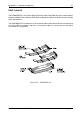
Remove Flat HD Screws
(11 Plcs) from Power
Supply Module Cover
Figure B-9: Power Supply Module Retaining Screws
3. Disconnect the following cables from the DS400 power strip:
All device power connectors
Chassis power switch connector
Chassis power LED connector
4. Carefully turn the DS400 over so that the fans on the back panel are positioned at the top
of the chassis.
5. Remove the eleven (11) Flat Hd. screws that secure the power supply module to the
chassis (Figure B-9).
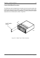
6. Lift the rear of the power supply module and remove (Figure B-10).
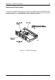
7. Reverse the procedures described in items 1 through 6 and install the new power supply
module.