StorCase® Technology Data Silo® DS400 External SCSI Expansion Chassis User's Guide
i StorCase® Technology Data Silo® DS400 External SCSI Expansion Chassis User's Guide Part No. D89-0000-0051 E01 January 2003 StorCase Technology, Inc. 17600 Newhope Street Fountain Valley, CA 92708-9885 Phone (714) 438-1850 Fax (714) 438-1847 DS400 User's Guide - Rev. E01 StorCase Technology, Inc.
ii LIMITED WARRANTY STORCASE TECHNOLOGY, Incorporated (StorCase) warrants that its products will be free from defects in material and workmanship, subject to the conditions and limitations set forth below. StorCase will, at its option, either repair or replace any part of its product that proves defective by reason of improper workmanship or materials.
iii Free Technical Support StorCase provides free technical support. If you experience any difficulty during the installation or subsequent use of a StorCase product, please contact StorCases Technical Support Department prior to servicing your system. This warranty covers only repair or replacement of defective StorCase products, as described above. StorCase is not liable for, and does not cover under warranty, any costs associated with servicing and/or installation of StorCase products.
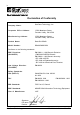
iv Declaration of Conformity Company Name: StorCase Technology, Inc.
v Important Safety Instructions 1. Read all these instructions. 2. Save these instructions for later use. 3. Follow all warnings and instructions marked on the product. 4. Do not use this product near water. 5. This product should be operated from the type of power source indicated on the marking label. If you are not sure of the type of power available, consult your dealer or local power company. 6.
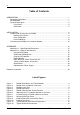
vi Table of Contents INTRODUCTION ..................................................................................................................... Packaging Information .................................................................................................. Serial Number ................................................................................................................ General Description ...........................................................................................
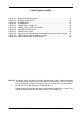
vii List of Figures (cont'd) Figure Figure Figure Figure Figure Figure Figure Figure Figure Figure Figure A-1: B-1: B-2: B-3: B-4: B-5: B-6: B-7: B-8: B-9: B-10: DS400 Physical Dimensions ...................................................................... SCSI Ultra160 Cable Kit ................................................................................ DCREMLVD-KIT ............................................................................................. DCW4RAID-KIT ........................
viii This Page Left Blank Intentionally. StorCase Technology, Inc. DS400 User's Guide - Rev.
Introduction 1 INTRODUCTION Packaging Information The StorCase Technology Data Silo® external expansion chassis is shipped in a container designed to provide protection and prevent damage during shipment. The Data Silo was carefully inspected before and during the packing procedure at the factory. Evidence of any damage to the Data Silo should be reported to the shipper immediately.
2 Introduction General Description The StorCase Technology Data Silo® DS400 SCSI expansion chassis provides rugged and reliable housing for 5.25" or 3.5" form factor, full-height, half-height, or low-profile (up to 1" high) SCSI devices. DS400 units accommodate standard SCSI hard disks, tape drives, optical drives, RAID controllers, and other SCSI devices, as well as the StorCase Data Express® removable device enclosures.
Introduction 3 This User's Guide describes the steps required for installing drive(s) into the Data Silo DS400 tower or rack mount external expansion chassis. For consistency, most illustrations depict the DS400 rack mount model. Although cosmetically different on the exterior, the tower and rack mount models are identical on the interior. Where appropriate, instructions and illustrations specific to the tower version of the DS400 are included.
4 Introduction Front Panel (Figure 3) Chassis Power-On Switch - Front-mounted rocker switch controls power to the chassis. Removable Drive Bay Partition - Removing this partition allows drives to be spaced apart for additional chassis ventilation. Removable Filler Panel - Accommodates removable media devices (e.g. CD-ROM, DAT drives, etc). Device Activity LED - Provides a visual indication of drive activity.
Introduction 5 Rear Panel (Figure 4) Cooling Fans - Four (4) back panel cooling fans provide high power cooling and ample chassis ventilation. SCSI I/O Connectors - The Data Silo DS400 can be equipped with 50-pin MM (HD50), 68-pin HD, or 68-pin VHDCI connectors (used for SCSI Ultra2 and Ultra160). Up to eight (8) SCSI channels are supported. A/C Power In - Accepts U.S. and other available international standard power cables.
6 Installation INSTALLATION Installing the Drive(s) Into the DS400 While performing the steps in this section, work on a soft surface to prevent excessive shock to the drive(s) and to protect the finish of the chassis. Refer to the documentation provided with the drive(s) to be installed to identify appropriate connectors, jumpers, and terminators on each. A #2 Phillips and a flat blade screwdriver will be required. Removing the Cover CAUTION: Remove ALL power from the DS400 before removing the cover.
Installation 7 Figure 5: DS400 Cable Access Cover Removal DS400 User's Guide - Rev. E01 StorCase Technology, Inc.
8 Installation Drive Preparation 1. Remove the drive from its protective packaging. 2. Plastic Drive Bezel - If installing a hard drive which is equipped with a plastic front bezel, remove the drive bezel. 3. SCSI Drive Termination - The last drive on any SCSI channel must have termination enabled. In most instances, depending upon the cable configuration, termination will be handled by an external terminator on the DS400 back panel. If using an external terminator, disable onboard drive termination.
Installation 9 Figure 6: Attaching the 3.5" Adapter Bracket to the Drive Power Connector Power Cable DS400 Power Strip 0579 Figure 7: Connecting the DC Power Cable to the Drive (Data Express Removable Enclosure shown) DS400 User's Guide - Rev. E01 StorCase Technology, Inc.
10 Installation Drive Installation 1. Remove the filler panels from the DS400 by gently prying the left or right edge of each filler panel with the tip of a flat blade screwdriver (Figure 8). 2. If installing fixed media devices, install the device activity and device fault LEDs into the appropriate front filler panels. Gently push each LED into the rear of the filler panel as shown in Figure 9.
Installation 11 3. Attach the drive activity and drive fault indicator LED cables to the appropriate drive pins (efer to the device manufacturer's documentation for the location of these pins). 4. Install the drive(s) into the drive mounting bracket using four (4) #6-32 Phillips screws (Figure 10). Be careful not to pinch or crimp attached cables. Do not fully tighten the screws at this point.
12 Installation 5. Reinstall the filler panel(s) that were removed earlier (fixed media devices only). Check the clearance between the newly installed drive(s) and the filler panel(s). If installing removable media devices, verify that the installed devices are flush with the DS400 front panel. 6. Tighten the drive mounting screws. 7. Connect the I/O cable(s) to the drive(s). Verify that the Pin 1 indicator on the cable is properly aligned (Figure 11).
Installation 13 Pin 1 Device 1 Device 2 Device 3 Device 4 (Empty Bay) Device 5 (Empty Bay) Channel 1 (2 Devices) Device 6 Device 7 Channel 2 (1 Device) Device 8 Device 9 Channel 3 (4 Devices) 0 40 el DS Pan k c Ba 0583 Figure 11: Typical Internal SCSI Cable Configuration NOTE: Internal wiring must be ordered separately [available with 50-pin MM (HD50), 68-pin HD, or 68-pin VHDCI rear panel connectors]. DS400 User's Guide - Rev. E01 StorCase Technology, Inc.
14 Installation Connecting the DS400 to a Computer System If the DS400 is the last SCSI device on the SCSI bus, it will require the appropriate termination for the I/O connector. Refer to Figure 12 below for typical single and multiple host external SCSI connections. Follow the directions that came with your computer system for cabling an external SCSI device to that system. Figure 12: Typical SCSI I/O Connections StorCase Technology, Inc. DS400 User's Guide - Rev.
Appendix A - Specifications/Dimensions 15 APPENDICES DS400 User's Guide - Rev. E01 StorCase Technology, Inc.
16 Appendix A - Specifications/Dimensions Appendix A - Specifications/Dimensions StorCase Technology, Inc. DS400 User's Guide - Rev.
Appendix A - Specifications/Dimensions 17 Figure A-1: DS400 Physical Dimensions (Dimensions are for reference only) DS400 User's Guide - Rev. E01 StorCase Technology, Inc.
18 Appendix B - Optional Accessories Appendix B - Optional Accessories Internal SCSI Cables For a complete and current listing of StorCase external cable, power cable, and terminator options that can be used with this product, please visit the StorCase web site at www.storcase.com.
Appendix B - Optional Accessories 19 Figure B-1: SCSI Ultra160 Cable Kit (DCULTRA160-9KIT shown) DS400 User's Guide - Rev. E01 StorCase Technology, Inc.
20 Appendix B - Optional Accessories 9-Drive LVD Cable Kit The DCREMLVD-KIT, an internal cable kit designed for the StorCase 9-bay Data Silo rack mount or tower chassis, allows the DS400 to be used for SCSI Ultra160 applications implementing certain Data Express removables. Contact StorCase for further information. The DCREMLVD-KIT (Figure B-2) consists of an internal 9-drive ribbon cable, LVD/S.E. terminator, and a VHDCI rear panel adapter card. Figure B-2: DCREMLVD-KIT StorCase Technology, Inc.
Appendix B - Optional Accessories 21 RAID Cable Kit The DCW4RAID-KIT, an internal cable kit for the Storcase 9-bay Data Silo rack or tower chassis, allows the DS400 to be used with SCSI RAID configurations where the RAID controller resides within the Data Silo. The DCW4RAID-KIT includes two (2) drive channel cables, each with 5 device connectors and an inline LVD/S.E. terminator, and one (1) host channel cable for connecting to the rear panel of the Data Silo (Figure B-3).
22 Appendix B - Optional Accessories Rack Mount -to-Tower Conversion Kit This kit provides all the parts necessary to convert an existing rack mount DS400 to a tower configuration, as shown in Figure B-4. The kit is available in a StorCase White finish (P/N DXTWR-KIT) and a black finish (P/N DXTWR-KIT/B). Figure B-4: DS400 Rack-To-Tower Kit StorCase Technology, Inc. DS400 User's Guide - Rev.
Appendix B - Optional Accessories 23 Tower-to-Rack Mount Conversion The DS400 tower model is shipped with two (2) handles and mounting screws located inside a plastic bag in the top cover of the chassis. These handles are provided so that the tower model may be converted to a rack mount configuration. To convert a tower model to a rack mount, remove the tower parts shown in Figure B-3 and attach the two (2) handles to the DS400 chassis with two (2) screws each as shown in Figure B-5.
24 Appendix B - Optional Accessories Slide Rail Kit The optional slide rail kit (P/N DXRCK-SLIDE) provides a convenient method to attach the DS400 to a rack mount enclosure (Figure B-6). The StroCase high quality, durable rails provide 24 ball bearing rollers and have a quick release button which allows quick and easy installation and removal of the DS400 unit from its rack enclosure. Contact StorCase for further ordering information. 0591 Figure B-6: Rack Mount Slide Rail Kit StorCase Technology, Inc.
Appendix B - Optional Accessories 25 Replacement Power Supply A replacement 300 watt power supply is available for the DS400 chassis (P/N DX400-PS300) as shown in Figure B-7. The DS400 power supply replacement should only be performed by qualified personnel. Contact StorCase for further ordering information. Figure B-7: DS400 Power Supply DS400 User's Guide - Rev. E01 StorCase Technology, Inc.
26 Appendix B - Optional Accessories Installing the Replacement Power Supply A power supply LED indicator is located on DS400 back panel (Figure C-8). When illuminated, this LED indicates that the power supply is functioning normally. If this indicator fails to illuminate when the chassis power is on, it is an indication that a problem with the power supply has occurred. If this is the case, replace the power supply module. A diagnostic connector (3.
Appendix B - Optional Accessories 27 3. Disconnect the following cables from the DS400 power strip: All device power connectors Chassis power switch connector Chassis power LED connector 4. Carefully turn the DS400 over so that the fans on the back panel are positioned at the top of the chassis. 5. Remove the eleven (11) Flat Hd. screws that secure the power supply module to the chassis (Figure B-9). 6. Lift the rear of the power supply module and remove (Figure B-10). 7.
28 Appendix B - Optional Accessories 0593 Figure B-10: Removing the Power Supply Module StorCase Technology, Inc. DS400 User's Guide - Rev.
Reader's Comments 29 Reader's Comments Please take a few moments when your computer system is up and running to send us your ideas and suggestions for improving our products and documentation.
Reader's Comments CUT ALONG THIS LINE FROM BOTTOM TO TOP OF PAGE 30 FOLD ALONG THIS LINE AND STAPLE SHUT NO POSTAGE NECESSARY IF MAILED IN THE UNITED STATES B U S I N E S S R E P LY M A I L FIRST CLASS MAIL PERMIT NO. 10686 SANTA ANA, CA POSTAGE WILL BE PAID BY ADDRESSEE TECHNOLOGY CORPORATION 17600 NEWHOPE STREET FOUNTAIN VALLEY CA 92708-9885 StorCase Technology, Inc. DS400 User's Guide - Rev.