
Manual

vii
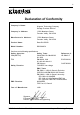
DS350 User's Guide - Rev. A00 Kingston Technology Company
NOTICE: This User's Guide is subject to periodic updates without notice. Please check Kingston's
website at http://www.kingston.com or contact your Kingston representative for the latest
revision of this document.
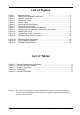
Table C-1: External Cables and Part Numbers .................................................................... 17
Table C-2: International Power Cables ................................................................................ 19
Table C-3: System Connectors ............................................................................................ 20
Table C-4: Terminators ......................................................................................................... 21
Table C-5: Internal SCSI Cables ........................................................................................... 23
List of Tables
List of Figures
Figure 1: Data Silo DS350 .............................................................................................. 2
Figure 2: DS350 Drive Installation Overview ............................................................... 3
Figure 3: DS350 Front Panel.......................................................................................... 4
Figure 4: DS350 Rear Panel .......................................................................................... 5
Figure 5: Access Panel ................................................................................................. 6
Figure 6: Removing the Drive Bracket .......................................................................... 7
Figure 7: Removing the Filler Panel ............................................................................... 8
Figure 8: Installing a Drive into the Drive Bracket ........................................................ 9
Figure 9: Installing the Drive/Bracket Assembly into the Chassis ............................... 9
Figure 10: DS350 Power Strip ...................................................................................... 10
Figure 11: Typical Daisy-Chain Connections................................................................ 11
Figure 12: Dual Host Daisy-Chain Connection .............................................................. 12
Figure A-1: DS350 Physical Dimensions ........................................................................ 15
Figure B-1: Drive Interface Adapters ............................................................................. 16
Figure D-1: Rack Mount Slide Rail Kit .............................................................................. 24