Kingston Technology Data Silo® DS350 External SCSI Expansion Chassis User's Guide
i Kingston Technology DS350 Data Silo® External SCSI Expansion Chassis User's Guide Part No. D89-0000-0089 A00 May 1999 Kingston Technology Company 17600 Newhope Street Fountain Valley, CA 92708-9885 Phone (714) 438-1850 Fax (714) 438-1847 DS350 User's Guide - Rev.
ii Kingston Storage Products Warranty & Return Guidelines KINGSTON TECHNOLOGY COMPANY'S STORAGE PRODUCT DIVISION warrants that its core products are free from defects in material and workmanship. Subject to the conditions and limitations set forth below, Kingston will, at its option, either repair or replace any part of its product that proves defective by reason of improper workmanship or materials.
iii Warranty Claim Requirements To obtain warranty service, the defective product must be returned to your local authorized Kingston dealer or distributor, or to the Kingston factory service center. For defective returns directly to Kingston, shipments must be freight-prepaid and insured, and must include the product serial number, a detailed description of the problem experienced, and proof of the original retail purchase date.
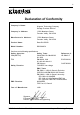
iv Declaration of Conformity Companys Name: Kingston Technology Company Storage Products Division Companys Address: 17600 Newhope Street Fountain Valley, CA 92708 Manufacturers Address: 17600 Newhope Street Fountain Valley, CA 92708 Product Name: Data Silo DS350 Model Number: DS350-XX/X Conforms to the following specifications: Safety Agencies: CSA (NRTL/C) TÜV Safety Directive: Safety Tests: CAN/CSA-C22.
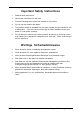
v Important Safety Instructions 1. Read all these instructions. 2. Save these instructions for later use. 3. Follow all warnings and instructions marked on the product. 4. Do not use this product near water. 5. This product should be operated from the type of power source indicated on the marking label. If you are not sure of the type of power available, consult your dealer or local power company. 6.
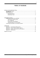
vi Table of Contents DATA SILO DS350 INTRODUCTION ..................................................................................... Packaging Information .................................................................................................. Serial Number ................................................................................................................ General Description ......................................................................................................
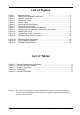
vii List of Figures Figure 1: Figure 2: Figure 3: Figure 4: Figure 5: Figure 6: Figure 7: Figure 8: Figure 9: Figure 10: Figure 11: Figure 12: Data Silo DS350 .............................................................................................. 2 DS350 Drive Installation Overview ............................................................... 3 DS350 Front Panel .......................................................................................... 4 DS350 Rear Panel ..........................
viii This Page Left Blank Intentionally. DS350 User's Guide - Rev.
Introduction 1 DATA SILO® DS350 INTRODUCTION Packaging Information The Kingston Technology Data Silo® external expansion chassis is shipped in a container designed to provide protection and prevent damage during shipment. The Data Silo was carefully inspected before and during the packing procedure at the factory. Evidence of any damage to the Data Silo should be reported to the shipper immediately.
2 Introduction General Description The Kingston Technology Data Silo® DS350 expansion chassis provides rugged and reliable housing for SCSI storage devices. The DS350 is designed to support 3.5 inch and 5.25 inch form factor, full-height, half-height, and low profile (1 inch high) removable media devices. The DS350 can house Kingston's own Data Express® removable drive enclosures as well. The DS350 is available in a rack mount, quad (4) bay configuration (Figure 1).
Introduction 3 This User's Guide describes the steps required for installing drive(s) into the DS350 external expansion chassis. This guide is intended to supplement documentation provided with the host computer system, the operating system, and the drive(s) to be installed within the DS350. Figure 2 below illustrates a typical drive installation into a DS350 external expansion chassis. Figure 2: DS350 Drive Installation Overview DS350 User's Guide - Rev.
4 Introduction DS350 Front Panel (See Figure 3) Chassis LED/Audio Indicator - Provides the following operating information: Green = Power On Red = Power Supply Failure (alarm will continually buzz) Flash Red = Fan Failure (alarm will continually buzz) Chassis Temperature Exceeds 40° C (alarm will intermittently buzz) Removable Filler Panel(s) - Accommodate up to four (4) low-profile or half-height, or two (2) full-height removable media devices (CD-ROM, DAT drives, etc.).
Introduction 5 DS350 Rear Panel (See Figure 4) Diagnostic Connector - Provides DS350 system status for diagnostic testing. Provides signals for: power supply status fan failure over temperature condition A Molex 3.00mm (0.118") pitch Micro-Fit plug (part number 4302) is provided on the DS350 back panel. A Molex 3.00mm (0.118") pitch Micro-Fit receptacle (part number 42025) is required for mating connection. The above signals are active low and require a 10K pull-up resistor.
6 Installation DS350 INSTALLATION Installing the Drive(s) into the DS350 While performing the steps in this section, work on a soft surface to prevent excessive shock to the drive(s) being installed. Also refer to the manufacturer's documentation provided with the drive(s). A #2 Phillips and a flat blade screwdriver will be required. Removing the Access Panel WARNING: Remove ALL power from the DS350 before removing the access panel. The DS350 contains NO USER SERVICEABLE PARTS inside the unit. 1.
Installation 7 Drive Preparation 1. Remove the drive from its protective packaging. 2. SCSI Drive Termination - The last drive on any SCSI channel must have termination enabled. In most instances, depending upon cable configuration, termination will be handled by an external terminator on the DS350 back panel. If using an external terminator, disable onboard termination. Refer to the documentation provided by the drive manufacturer for the location of these terminators or jumpers.
8 Installation Installing the Drive into the Bracket NOTE: Removal of the filler panel(s) is required in order to install the drive(s) into the drive bracket. 1. Remove filler panel(s) by applying gentle pressure to the tabs with the tip of a flat blade screwdriver (Figure 7). Figure 7: Removing the Filler Panel 2. Install the drive(s) into the drive bracket. Drive(s) must be side-mounted to the drive brackets using either M3 or #6-32 screws (Figure 8).
Installation 9 Figure 8: Installing a Drive into the Drive Bracket Figure 9: Installing the Drive/Bracket Assembly into the Chassis DS350 User's Guide - Rev.
10 Installation 5. Connect the I/O cable(s) to the drive(s). Verify that the Pin 1 indicator on the cable is properly aligned (Refer to the drive manufacturer's documentation for more information). 6. Connect the 4-pin DC power cable(s) from the DS350 power strip to the drive(s) (Figure 10). Figure 10: DS350 Power Strip 7. Reinstall the access panel and fasten all screws. 8. Connect the AC power cable to the DS350 and turn on power. Should there be any unusual sound, turn the DS350 off immediately.
Installation 11 Connecting the DS350 to the Computer System If the DS350 is the last device in a SCSI daisy chain, it will require the appropriate termination (Figures 11 and 12). Refer to Appendix C for available terminators. The DS350 is can be configured with two (2) external rear panel SCSI I/O connectors designed for a single host (single-port) connection, or four (4) rear panel SCSI I/O connectors designed for dual host (dual-port) connection.
12 Installation Figure 12: Dual Host Daisy-Chain Connection Kingston Technology Company DS350 User's Guide - Rev.
Appendix A - Specifications/Dimensions 13 Appendices DS350 User's Guide - Rev.
14 Appendix A - Specifications/Dimensions Appendix A - Specifications/Dimensions SCSI Data Silo chassis conform to the Small Computer Systems Interface (SCSI) Standard set by the American National Standards Institute (ANSI). The following DS350 specifications and dimensions are provided for reference only. Kingston Technology Company DS350 User's Guide - Rev.
Appendix A - Specifications/Dimensions 15 Figure A-1: DS350 Physical Dimensions (Dimensions are for reference only) DS350 User's Guide - Rev.
16 Appendix B - Drive Interface Adapters Appendix B - Drive Interface Adapter Options Kingston provides several drive interface adapter options that permit various DS350/drive connector combinations. Contact Kingston for additional ordering information. Adapts 16-bit, 68-pin Wide device to 8-bit, 50-pin SCSI cable connector. Adapts 16-bit, 68-pin SCSI cable connector to Single-Connect (SCA) drive interface connector (includes power, ID selection and device activity connections).
Appendix C - Cables, Connectors, and Terminators 17 Appendix C - Cables, Connectors, and Terminators Table C-1: External Cables and Part Numbers DS350 User's Guide - Rev.
18 Appendix C - Cables, Connectors, and Terminators Table C-1: External Cables and Part Numbers (cont'd) (Not to scale - Illustration is for reference only) Kingston Technology Company DS350 User's Guide - Rev.
Appendix C - Cables, Connectors, and Terminators Table C-2: Model Number 19 International Power Cables Country DC100-US United States DC100-CE Continental Europe DC100-UK United Kingdom DC100-SW Switzerland DC100-IT Italy DC100-AZ Australia/New Zealand Cable Type 0301 The DS350 is shipped with one (1) power cable per chassis. Please specify the appropriate part number if ordering non-U.S. cables. DS350 User's Guide - Rev.
20 Appendix C - Cables, Connectors, and Terminators Table C-3: System Connectors Note: Not all connector/cable configurations illustrated are available from Kingston. (Not to scale - Illustration is for reference only) Kingston Technology Company DS350 User's Guide - Rev.
Appendix C - Cables, Connectors, and Terminators Table C-4: 21 Terminators (Not to scale - Illustration is for reference only) DS350 User's Guide - Rev.
22 Appendix C - Cables, Connectors, and Terminators Table C-4: Terminators (continued) (Not to scale - Illustration is for reference only) Kingston Technology Company DS350 User's Guide - Rev.
Appendix C - Cables, Connectors, and Terminators 23 Table C-5: Internal SCSI Cables DS350 User's Guide - Rev.
24 Appendix D - Slide Rail Kit Appendix D - Slide Rail Kit The optional slide rail kit (Part Number DXRCK-SLIDE) provides a convenient method to attach the DS350 to a rack mount enclosure (Figure D-1). Kingston's high quality, durable rails provide 24 ball bearing rollers and have a quick release button which allows quick and easy installation and removal of the DS350 unit from its rack enclosure. Contact Kingston for further ordering information.
Reader's Comments 25 READERS COMMENTS Please take a few moments when your computer system is up and running to send us your ideas and suggestions for improving our products and documentation.
Reader's Comments CUT ALONG THIS LINE FROM BOTTOM TO TOP OF PAGE 26 FOLD ALONG THIS LINE AND STAPLE SHUT NO POSTAGE NECESSARY IF MAILED IN THE UNITED STATES B U S I N E S S R E P LY M A I L FIRST CLASS MAIL PERMIT NO. 10686 SANTA ANA, CA POSTAGE WILL BE PAID BY ADDRESSEE TECHNOLOGY CORPORATION 17600 NEWHOPE STREET FOUNTAIN VALLEY CA 92708-9885 Kingston Technology Company DE350 User's Guide - Rev.