StorCase® Technology Data Silo® DS321 External FireWire 800-to-IDE Expansion Chassis User's Guide
i StorCase® Technology Data Silo® DS321 External FireWire 800-to-IDE Expansion Chassis User's Guide Part No. D89-0000-0213 B00 April 2004 StorCase Technology, Inc. 17600 Newhope Street Fountain Valley, CA 92708-9885 Phone (714) 438-1850 Fax (714) 438-1847 DS321 User's Guide - Rev. B00 StorCase Technology, Inc.
ii LIMITED WARRANTY STORCASE TECHNOLOGY, Incorporated (StorCase) warrants that its products will be free from defects in material and workmanship, subject to the conditions and limitations set forth below. StorCase will, at its option, either repair or replace any part of its product that proves defective by reason of improper workmanship or materials.
iii Warranty Claim Requirements To obtain warranty service, the defective product must be returned to your local authorized StorCase dealer or distributor, or, with prior StorCase approval, to the StorCase factory service center. For defective products returned directly to StorCase, a Return Material Authorization (RMA) number must be obtained by calling StorCase Customer Service at (714) 445-3455. The RMA number must be prominently displayed on the outside of the return package.
iv Declaration of Conformity Company Name: StorCase Technology, Inc.
v Important Safety Instructions 1. Read all these instructions. 2. Save these instructions for later use. 3. Follow all warnings and instructions marked on the product. 4. Do not use this product near water. 5. This product should be operated from the type of power source indicated on the marking label. If you are not sure of the type of power available, consult your dealer or local power company. 6.
vi Table of Contents INTRODUCTION ..................................................................................................................... Packaging Information .................................................................................................. Serial Number ................................................................................................................ General Description ...........................................................................................
vii List of Figures Figure 1: Figure 2: Figure 3: Figure 4: Figure 5: Figure 6: Figure 7: Figure 8: Figure 9: Figure 10: Figure 11: Data Silo DS321 .............................................................................................. 2 Front Panel ...................................................................................................... 5 Rear Panel ...................................................................................................... 6 Drive Installation Assembly ....
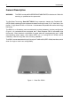
Introduction 1 INTRODUCTION Packaging Information The StorCase Technology Data Silo® external expansion chassis is shipped in a container designed to provide protection and prevent damage during shipment. The Data Silo was carefully inspected before and during the packing procedure at the factory. Evidence of any damage to the Data Silo should be reported to the shipper immediately.
2 Introduction General Description WARNING: The DS321 contains NO USER SERVICEABLE PARTS inside the unit. Refer ALL servicing to qualified service personnel! The StorCase Technology Data Silo® DS321 2-bay expansion chassis with FireWire 800 (IEEE-1394b) interface provide durable and reliable mounting for two (2) 3.5" form factor, lowprofile (1" high) Ultra ATA100 or 133 drives. It is downward compatible with earlier technology IDE drives.
Introduction 3 This User's Guide describes the steps required for installing drive(s) into the Data Silo DS321external expansion chassis. This guide is intended to supplement documentation provided with the host computer system, the operating system, and the drive(s) to be installed within the Data Silo.
4 Introduction Front Panel (Figure 2) Data Express® DE110 Removable Drive Carrier(s) - Provides durable and reliable mounting for low-profile 3.5" Ultra ATA100 or 133 drives (downward-compatible with earlier technology IDE drives). Key Lock/Drive Power Switch(es) - Perform three functions. The key switch assures proper seating of the drive carrier within the receiving frame, turns power to the drive on and off, and prevents unauthorized removal or installation of the carrier.
Introduction 5 DE110 Removable Drive Carrier Drive Ready LED Key Lock Drive Activity LED 321_03 Carrier Handle Error LED Figure 2: Front Panel DS321 User's Guide - Rev. B00 StorCase Technology, Inc.
6 Introduction Rear Panel (Figure 3) FireWire Interfaces - Connect to a FireWire 800 (IEEE-1394b) device via FireWire800 cable (provided). Dual connectors allow for single or dual host configurability. Refer to section "Typical FireWire Configurations" for further information. Fan - One (1) cooling fan provides chassis ventilation (5.5 CFM). Fan Override Switch OFF = (Recommended) Cooling fan is ON when chassis is on (Factory Default). ON = Fan Override is enabled. Cooling fan is DISABLED.
Installation 7 INSTALLATION CAUTION: The DS321 chassis contains NO USER SERVICEABLE parts inside the unit. Refer ALL servicing to qualified personnel! NOTE: Refer to the Data Express DE110 User's Guide for additional operating and installation information. Also refer to the disk manufacturer's documentation for specific information regarding the disks. Drive Preparation 1. Remove the drive from its protective packaging. 2.
8 Installation Drive Installation 1. Remove the DE110 drive carrier(s) from the DS321 chassis. 2. Uninstall the drive cover(s) from the drive carrier(s). Refer to Figure 5. 3. Attach the DC power cable (from the Drive Carrier Board) to the drive (Figure 4). 4. Carefully insert the drive into the carrier. Slide the drive towards the Drive Carrier Board, so that the I/O connector on the drive mates with the connector on the Drive Carrier Board (Figure 4).
Installation 9 1 Insert this end into the carrier first 2 Slide the cover towards the back of the carrier 0836 3 Secure with #6-32 Phillips Flat Hd. screws (2 Total) Figure 5: Drive Cover Installation 7. The DE110 drive carrier is now ready to be inserted into the Data Silo. NOTE: 8. The lock on the DE110 carrier functions as a lock and a DC power switch for the carrier unit. The lock must be engaged in order to supply power to the carrier and installed drive. Reboot the computer.
10 Installation Desktop Conversion NOTE: All necessary desktop conversion hardware is included in the DS321 accessory bag. 1. Unplug the DS321 and verify that ALL cables have been disconnected. 2. Turn the DS321 over and place it on a soft clean surface, so that the bottom is facing upward. 3. Peel paper backing off rubber feet (4 total) and press into place (location indicated by "L" marks) as shown in Figure 6.
Installation 11 Rack Mount Conversion NOTE: All necessary rack mount conversion hardware is included in the DS321 accessory bag. 1. Unplug the DS321 and verify that ALL cables have been disconnected. 2. Place DS321 on a soft clean surface. 3. Attach each bracket with four (4) black #6-32 Phillips Flat Hd. screws as shown in Figure 7. DS321 Chassis Attach with 4 Black Screws (Included) 321_13 Bracket (1 per Side) Figure 7: Rack Mount Conversion DS321 User's Guide - Rev.
12 Installation Typical FireWire Configurations NOTES: The installation, configuration, and use of the StorCase Data Silo DS321 FireWire 800-to-IDE chassis requires a certain level of expertise and experience on the part of the user/integrator. Since there are many configuration options and variables (ie. host platforms, applications, etc), only general/typical configuration guidelines will be discussed in this User's Guide.
Installation 13 20 FireWire 800 Cable (Provided) FireWire Host 20 FireWire 800 Cable (Provided) 20 FireWire 800 Cable (Optional) 6 FireWire 800 Cable (Provided) 321_06 Figure 9: Typical Single Host Connection to Multiple Data Silos DS321 User's Guide - Rev. B00 StorCase Technology, Inc.
14 Installation Typical Dual Host Configurations NOTE: Depending on configuration, additional FireWire cabling may be required. Contact StorCase for further ordering information. 6 FireWire 800 Cable (Optional) FireWire Host 6 FireWire 800 Cable (Provided) 321_07 FireWire Host Figure 10: Typical Dual Host Connection to One Data Silo StorCase Technology, Inc. DS321 User's Guide - Rev.
Installation 15 6 FireWire 800 Cable (Provided) FireWire Host 6 FireWire 800 Cable (Provided) FireWire Host 20 FireWire 800 Cable (Provided) 20 FireWire 800 Cable (Provided) 321_08 Figure 11: Typical Dual Host Connection to Multiple Data Silos DS321 User's Guide - Rev. B00 StorCase Technology, Inc.
16 Installation This Page Left Blank Intentionally. StorCase Technology, Inc. DS321 User's Guide - Rev.
Appendix A - Specifications/Dimensions 17 APPENDICES DS321 User's Guide - Rev. B00 StorCase Technology, Inc.
18 Appendix A - Specifications/Dimensions Appendix A - Specifications/Dimensions The following DS321 specifications and dimensions are provided for reference only. 0 C to 40 C -40 C to 70 C -1000 to 10,000 ft -1000 to 40,000 ft -305m to 3048m -305m to 12195m Compliance 1.73 (43.9mm) 14.06 (357.1mm) 14.05 (356.9mm) IEEE-1394b & ATA-5 Max. Transfer Rate up to 800Mbps Max. Cable Length 4.5m (14.75 ft) 13.5 lbs (6.1kg) Width of desktop version Total weight including 2 DE110 carriers (10.
Appendix A - Specifications/Dimensions 14.05 (356.9mm) Front View (Desktop Version) 19 Top View Right Side View 1.73 (43.9mm) 321_dims 14.06 (357.1mm) Front View (Rack Mount Version) 18.98 (482.1mm) Figure A-1: DS321 Physical Dimensions (Dimensions are for reference only) DS321 User's Guide - Rev. B00 StorCase Technology, Inc.
20 Appendix B - Optional Accessories Appendix B - Optional Accessories FireWire Cables Additional FireWire cables are available for the DS321 as shown in Figure B-1. Contact StorCase for further ordering information. 321_15 6 ft. Beta-to-Beta (FireWire 800-to-FireWire 800) Cable 20 in. Beta-to-Beta (FireWire 800-to-FireWire 800) Cable Figure B-1: StorCase Technology, Inc. 6 ft. Bilingual-to-6 circuit 1394a (FireWire 800-to-FireWire 400) Cable FireWire Cables DS321 User's Guide - Rev.
Appendix B - Optional Accessories 21 Removable Drive Carriers Additional DE110 removable drive carriers are available for the DS321 as shown in Figure B-2. Contact StorCase for further ordering information. 320FW_12 Figure B-2: DE110 Drive Carrier DS321 User's Guide - Rev. B00 StorCase Technology, Inc.
22 Appendix B - Optional Accessories Carrying Case (Figure B-3) The optional molded plastic carrying case (P/N S20E101) is designed to transport the DE110 drive carrier from one site to another in a safe, impact and moisture resistant environment. Its compact dimensions, 7" long x 9" wide x 4" high, make it easy to carry and store. The foam lining is contoured to fit a single DE110 carrier. Contact StorCase for further ordering information. 320FW_13 Figure B-3: Carrying Case StorCase Technology, Inc.
Reader's Comments 23 Reader's Comments Please take a few moments when your computer system is up and running to send us your ideas and suggestions for improving our products and documentation.
Reader's Comments CUT ALONG THIS LINE FROM BOTTOM TO TOP OF PAGE 24 FOLD ALONG THIS LINE AND STAPLE SHUT NO POSTAGE NECESSARY IF MAILED IN THE UNITED STATES B U S I N E S S R E P LY M A I L FIRST CLASS MAIL PERMIT NO. 10686 SANTA ANA, CA POSTAGE WILL BE PAID BY ADDRESSEE TECHNOLOGY CORPORATION 17600 NEWHOPE STREET FOUNTAIN VALLEY CA 92708-9885 StorCase Technology, Inc. DS321 User's Guide - Rev.