StorCase® Technology Data Silo® DS320 External SCSI Expansion Chassis User's Guide
i StorCase® Technology Data Silo® DS320 External SCSI Expansion Chassis User's Guide Part No. D89-0000-0115 B02 June 2003 StorCase Technology, Inc. 17600 Newhope Street Fountain Valley, CA 92708-9885 Phone (714) 438-1850 Fax (714) 438-1847 DS320 User's Guide - Rev. B02 StorCase Technology, Inc.
ii LIMITED WARRANTY STORCASE TECHNOLOGY, Incorporated (StorCase) warrants that its products will be free from defects in material and workmanship, subject to the conditions and limitations set forth below. StorCase will, at its option, either repair or replace any part of its product that proves defective by reason of improper workmanship or materials.
iii Free Technical Support StorCase provides free technical support. If you experience any difficulty during the installation or subsequent use of a StorCase product, please contact StorCases Technical Support Department prior to servicing your system. This warranty covers only repair or replacement of defective StorCase products, as described above. StorCase is not liable for, and does not cover under warranty, any costs associated with servicing and/or installation of StorCase products.
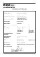
iv Declaration of Conformity Company Name: StorCase Technology, Inc.
v Important Safety Instructions 1. Read all these instructions. 2. Save these instructions for later use. 3. Follow all warnings and instructions marked on the product. 4. Do not use this product near water. 5. This product should be operated from the type of power source indicated on the marking label. If you are not sure of the type of power available, consult your dealer or local power company. 6.
vi Table of Contents INTRODUCTION ..................................................................................................................... Packaging Information .................................................................................................. Serial Number ................................................................................................................ General Description ...........................................................................................
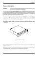
vii List of Figures Figure 1: Figure 2: Figure 3: Figure 4: Figure 5: Figure 6: Figure 7: Figure 8: Figure 9: Figure 10: Figure 11: Figure 12: Data Silo DS320 .............................................................................................. 2 DS320 Front Panel .......................................................................................... 3 DS320 Rear Panel .......................................................................................... 4 Access Panel ....................
Introduction 1 INTRODUCTION Packaging Information The StorCase Technology Data Silo® external expansion chassis is shipped in a container designed to provide protection and prevent damage during shipment. The Data Silo was carefully inspected before and during the packing procedure at the factory. Evidence of any damage to the Data Silo should be reported to the shipper immediately.
2 Introduction General Description WARNING: The DS320 contains NO USER SERVICEABLE PARTS inside the unit. Refer ALL servicing to qualified service personnel! The StorCase Technology Data Silo® DS320 expansion chassis provides rugged and reliable housing for SCSI storage devices. The DS320 is designed to support 3.5" and 5.25" form factor, full-height, half-height, and low profile (1" high) removable media devices. The DS320 can house Data Express® removable drive enclosures as well.
Introduction 3 Front Panel (Figure 2) Chassis Status LED/Audio Indicator - Provides the following operating information: GREEN RED = Steady glow indicates power ON = Flashing indicates Fan Failure (alarm will sound) SCSI ID Select Switch(es) - Provide SCSI ID selection. The Data Silo uses two (2) rotating switches (refer to "Selecting the SCSI ID Number" for additional information). Device Fault LED - Provides a visual indication of the status for each installed drive.
4 Introduction Rear Panel (Figure 3) SCSI I/O Connector(s) - The DS320 is available with 50-pin MM (HD50), 68-pin HD, or 68-pin VHDCI connections. Up to two (2) SCSI channels can be supported. Blower(s) - Two (2) blowers provide ample chassis ventilation (11.3 CFM each). A/C Power In - Accepts U.S. and other available international standard power cables. Contact StorCase for ordering information. Fan Speed Selector Switch - High and low speed.
Installation 5 INSTALLATION Installing the Drive(s) into the DS320 While performing the steps in this section, work on a soft surface to prevent excessive shock to the drive(s) being installed. Also refer to the manufacturer's documentation provided with the drive(s). A #2 Phillips and a flat blade screwdriver will be required. Removing the Access Panel WARNING: Remove ALL power from the DS320 before removing the access panel. The DS320 contains NO USER SERVICEABLE PARTS inside the unit.
6 Installation Drive Preparation 1. Remove the drive from its protective packaging. 2. SCSI Drive Termination - The last drive on any SCSI channel must have termination enabled. In most instances, depending upon cable configuration, termination will be handled by an external terminator on the DS320 back panel. If using an external terminator, disable onboard termination. Refer to the documentation provided by the drive manufacturer for the location of these terminators or jumpers.
Installation 7 Installing the Drive into the Bracket NOTE: 1. Removal of the filler panel(s) is recommended for the installation of the drive(s) into the drive bracket. Carefully remove filler panel(s) by applying pressure to the tabs with the tip of a flat blade screwdriver (Figure 6).
8 Installation Figure 7: Attaching the 3.5" Adapter Brackets to the Drive Figure 8: Installing a Drive into the Drive Bracket StorCase Technology, Inc. DS320 User's Guide - Rev.
Installation 9 Figure 9: Installing the Drive/Bracket Assembly into the Chassis 5. Connect the I/O cable(s) to the drive(s). Verify that the Pin 1 indicator on the cable is properly aligned (refer to the drive manufacturer's documentation for more information). 6. Connect the 4-pin DC power cable(s) from the DS320 to the drive(s). 7. Reinstall the access panel and fasten all screws. 8. Connect the AC power cable to the DS320 and turn on power.
10 Installation Selecting the SCSI ID Number The SCSI ID is an address number (0-7 for 8-bit protocol and 0-15 for 16-bit protocol) that is assigned to each SCSI device. Each device in the chain must have a unique SCSI ID number. SCSI ID 7 is usually reserved for the host controller. If the computer system is already equipped with internal or external SCSI storage devices, some ID numbers will already be reserved.
Installation 11 IF INSTALLING AN 8-BIT SCSI DEVICE: The unit ID cable contains black, brown, red/black, and orange wires. Attach three (3) connectors from the SCSI ID select cable to the appropriate 2mm drive pins (Figure 11). The fourth (orange) wire is not used for the 8-bit installation. The single black wire plugs into the drive pin used to select ID1, the brown wire plugs into the drive pin for ID2, the red/black wire plugs into the drive pin for ID4. The orange wire is not used for this interface.
12 Installation IF INSTALLING A 16-BIT SCSI DEVICE: The unit ID cable contains black, brown, red/black, and orange wires. Attach four (4) connectors from the SCSI ID select cable to the appropriate 2mm drive pins (Figure 12). The single black wire plugs into the drive pin used to select ID1, the brown wire plugs into the drive pin for ID2, the red/black wire plugs into the drive pin for ID4 and the orange wire plugs into the drive pin to select ID8.
Appendix A - Specifications/Dimensions 13 APPENDICES DS320 User's Guide - Rev. B02 StorCase Technology, Inc.
14 Appendix A - Specifications/Dimensions Appendix A - Specifications/Dimensions SCSI Data Silo chassis conform to the Small Computer Systems Interface (SCSI) Standard set by the American National Standards Institute (ANSI). The following DS320 specifications and dimensions are provided for reference only. StorCase Technology, Inc. DS320 User's Guide - Rev.
Appendix A - Specifications/Dimensions 15 Figure A-1: DS320 Physical Dimensions (Dimensions are for reference only) DS320 User's Guide - Rev. B02 StorCase Technology, Inc.
16 Appendix B - Drive Interface Adapter Options Appendix B - Drive Interface Adapter Options StorCase provides several drive interface adapter options that permit various DS320/drive connector combinations. Contact StorCase for additional ordering information. Adapts 16-bit, 68-pin SCSI Wide device to 8bit, 50-pin SCSI Narrow cable connector. Adapts 16-bit, 68-pin SCSI Wide cable connector to Single-Connect (SCA) drive inteface connector (includes power, ID selection and device activity connections).
Reader's Comments 17 Reader's Comments Please take a few moments when your computer system is up and running to send us your ideas and suggestions for improving our products and documentation.
Reader's Comments CUT ALONG THIS LINE FROM BOTTOM TO TOP OF PAGE 18 FOLD ALONG THIS LINE AND STAPLE SHUT NO POSTAGE NECESSARY IF MAILED IN THE UNITED STATES B U S I N E S S R E P LY M A I L FIRST CLASS MAIL PERMIT NO. 10686 SANTA ANA, CA POSTAGE WILL BE PAID BY ADDRESSEE TECHNOLOGY CORPORATION 17600 NEWHOPE STREET FOUNTAIN VALLEY CA 92708-9885 StorCase Technology, Inc. DS320 User's Guide - Rev.