StorCase Technology Data Express® DE90i-A66 Removable Ultra ATA/66 Drive Enclosure User's Guide
i StorCase Technology Data Express® DE90i-A66 Removable Ultra ATA/66 Drive Enclosure User's Guide Part No. D89-0000-0111 A01 July 2000 StorCase Technology, Inc. 17600 Newhope Street Fountain Valley, CA 92708-9885 Phone (714) 438-1850 Fax (714) 438-1847 DE90i-A66 User's Guide - Rev. A01 StorCase Technology, Inc.
ii LIMITED WARRANTY STORCASE TECHNOLOGY, INC. ("StorCase") warrants that the following products will be free from defects in material and workmanship for a period of seven (7) years from the date of purchase from StorCase or its authorized reseller: all Data Silo® and Data Stacker® external expansion chassis, all Data Express® removable device enclosures and all StorCase interface cables and accessories specifically intended for use with these products.
iii Disclaimers The foregoing is the complete warranty for the products identified above and supersedes all other warranties and representations, whether oral or written. StorCase expressly disclaims all warranties for the identified products which are not stated herein, including, to the extent permitted by applicable law, any implied warranty of merchantability or fitness for a particular purpose.
iv Declaration of Conformity Company Name: StorCase Technology, Inc. Corporate Office Address: 17600 Newhope Street Fountain Valley, CA 92708 Manufacturing Address: 3400 S.
v Table of Contents DATA EXPRESS DE90i-A66 INTRODUCTION ...................................................................... Packaging Information .................................................................................................. Package Contents ......................................................................................................... Serial Numbers ..............................................................................................................
vi List of Tables Table 1: Table 2: Table 3: Shipping Contents ................................................................................................ 1 Receiving Frame Front Panel Indicator Conditions ............................................. 4 IDE Interface Signals .......................................................................................... 10 NOTICE: This User's Guide is subject to periodic updates without notice. Please check the StorCase website at http://www.storcase.
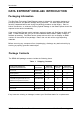
Introduction 1 DATA EXPRESS® DE90i-A66 INTRODUCTION Packaging Information The StorCase Technology Data Express system is shipped in a container designed to provide protection and prevent damage during shipment. The Data Express unit was carefully inspected before and during the packing procedure at the factory. Bent or broken connectors, or evidence of other physical damage to the Data Express should be reported to the carrier immediately.
2 Introduction Serial Numbers Both the Data Express receiving frame and carrier are labeled with serial numbers. These numbers must be reported to the StorCase Customer Service Representative in order to receive a Return Material Authorization (RMA) for warranty claims. Locate the serial number labels and record the numbers in the spaces provided below. Receiving Frame: Drive Carrier: StorCase Technology, Inc. DE90i-A66 User's Guide - Rev.
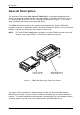
Introduction 3 General Description The StorCase Technology Data Express® DE90i-A66 is a removable lightweight drive carrier and receiving frame designed to provide durable and reliable mounting for one (1) 3.5 Ultra ATA/66 drive within a 5.25" half-height peripheral slot (Figure 1). It is downward compatible with earlier technology IDE drives.
4 Introduction Receiving Frame Front Panel (Refer to Figure 2) The Key Lock/Drive Power Switch performs three (3) functions. The key lock assures proper seating of the device carrier within the receiving frame, turns power to the device carrier on and off, and prevents unauthorized removal or installation of the carrier. For the computer to access data on the DE90i-A66 drive, the key must be turned counterclockwise to the locked position.
Introduction 5 Receiving Frame Rear Panel (Refer to Figure 3) DC Power Connector (J3): The DE90i-A66 uses a standard 4-pin DC Power Connector to accept DC power. I/O Connector (J2): The input/output connector provides a standard interface for all IDE signals. See Table 3 for J2 pin assignments. Master/Slave Selection Jumper (J5): Master Drive configuration (default). Forces Master Drive configuration on receiving frame. Change jumper to set Slave Drive configuration.
6 Installation DE90i-A66 INSTALLATION Installing the Drive in the Carrier Preparation While performing the steps in this section, work on a soft surface to prevent excessive shock to the drive being installed. Also refer to the manufacturer's documentation provided with the drive. NOTE: A #2 Phillips screwdriver will be required during this procedure. 1. Remove the drive from its protective packaging. 2.
Installation 7 Drive Activity Indicator Connector (J5) Jumper removed (factory default) disables drive activity indicator (Figure 4). Jumper installed enables drive activity indicator. NOTE: If two (2) drives are installed (with J5 enabled on both drives), both drive activity indicators will flash simultaneously, even if only one drive is being accessed. Installation 1. Attach the I/O cable from the drive carrier circuit board of the DE90i-A66 to the drive (Figure 5). 2.
8 Installation Installing the Receiving Frame The drive should be installed into the carrier before installing the receiving frame into the mounting bay of a computer or expansion chassis. NOTE: Use a #2 Phillips screwdriver during this procedure. 1. Turn OFF power to the computer. 2. Open the computer system according to the manufacturers instructions. If necessary, temporarily remove any expansion boards that may make installation difficult. 3.
Installation 9 Figure 7: Receiving Frame Mounting Holes 6. Connect the I/O cable from the host adapter to the receiving frame. The Pin 1 indicator on the cable must be properly aligned. Refer to Figure 3 for the correct Pin 1 location. 7. Connect the power cable from the DC power supply in the computer or expansion chassis to the power connector on the DE90i-A66 receiving frame. Refer to Figure 3 for the receiving frame power connector location. 8.
10 Installation IDE Interface Connector J2 The IDE interface connector (J2) pin assignments are as follows: Table 3: IDE Interface Signals Pin 01 03 05 07 09 11 13 15 17 19 21 23 25 27 29 31 33 35 37 39 Signal Host ResetHost Data 7 Host Data 6 Host Data 5 Host Data 4 Host Data 3 Host Data 2 Host Data 1 Host Data 0 Ground DMARQ DIOWDIORReserved Reserved IRQ 14 Host ADDR 1 Host ADDR 0 Host CS0DASP- I/O O I/O I/O I/O I/O I/O I/O I/O I/O O O O I O O O Notes Pin 02 04 06 08 10 12 14 16 18 20 22 24 26 28 3
Appendix A - Specifications/Dimensions 11 APPENDICES DE90i-A66 User's Guide - Rev. A01 StorCase Technology, Inc.
12 Appendix A - Specifications/Dimensions Appendix A - Specifications/Dimensions StorCase Technology, Inc. DE90i-A66 User's Guide - Rev.
Appendix A - Specifications/Dimensions 13 Figure A-1: DE90i-A66 Physical Dimensions (Dimensions are for reference only) DE90i-A66 User's Guide - Rev. A01 StorCase Technology, Inc.
14 Appendix B - Attaching the ON/OFF Key Appendix B - Attaching the ON/OFF Key The following information will provide the necessary steps to attach the ON/OFF key to the key lock mechanism so that it is non-removable, preventing accidental key loss. The procedure can be reversed at a later date to revert back to a removable key. 1. Make certain power is OFF to the receiving frame. Locate the rectangular shaped key lock mechanism access hole on the inside of the receiving frame.
Reader's Comments 15 Reader's Comments Please take a few moments when your computer system is up and running to send us your ideas and suggestions for improving our products and documentation.
Reader's Comments CUT ALONG THIS LINE FROM BOTTOM TO TOP OF PAGE 16 FOLD ALONG THIS LINE AND STAPLE SHUT NO POSTAGE NECESSARY IF MAILED IN THE UNITED STATES B U S I N E S S R E P LY M A I L FIRST CLASS MAIL PERMIT NO. 10686 SANTA ANA, CA POSTAGE WILL BE PAID BY ADDRESSEE TECHNOLOGY CORPORATION 17600 NEWHOPE STREET FOUNTAIN VALLEY CA 92708-9885 StorCase Technology, Inc. DE90i-A66 User's Guide - Rev.