
Instruction Manual


v
DE90i-A User's Guide - Rev. B02 StorCase Technology, Inc.
Table of Contents
INTRODUCTION ..................................................................................................................... 1
Packaging Information .................................................................................................. 1
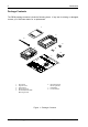
Package Contents ......................................................................................................... 1
Serial Numbers .............................................................................................................. 2
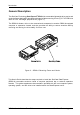
General Description ...................................................................................................... 3
Receiving Frame Front Panel ............................................................................... 4
Receiving Frame Rear Panel................................................................................ 5
INSTALLATION ...................................................................................................................... 7
Installing the Drive in the Carrier .................................................................................. 7
Preparation ............................................................................................................ 7
Configuring the Drive Carrier Circuit Board (Method 2) ..................................... 7
Installation ........................................................................................................... 12
Installing the Receiving Frame ................................................................................... 13
APPENDICES ........................................................................................................................ 17
Appendix A - Specifications/Dimensions .................................................................. 18
Appendix B - Attaching the ON/OFF Key .................................................................. 20
Reader's Comments ............................................................................................................ 21
List of Figures
Figure 1: DE90i-A Receiving Frame and Carrier ............................................................. 3
Figure 2: Receiving Frame Front Panel ............................................................................ 4
Figure 3: Receiving Frame (Rear View) .......................................................................... 6
Figure 4: DE90i-A Carrier Circuit Board ........................................................................... 8
Figure 5: Typical AT/IDE Drive Connections .................................................................. 11
Figure 6: Drive Installation Assembly ............................................................................. 12
Figure 7: Master/Slave Configuration Jumper J4A ....................................................... 13
Figure 8: Receiving Frame Mounting Holes ................................................................... 14
Figure A-1: DE90i-A Physical Dimensions ........................................................................ 19
Figure B-1: Attaching the ON/OFF Key ............................................................................ 20