
Instruction Manual


DE90i-A User's Guide - Rev. B02 StorCase Technology, Inc.
Installation 11
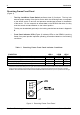
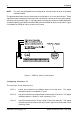
Figure 6: Typical AT/IDE Drive Connections
Typical AT/IDE drive jumper positions are shown in Figure 6. Remove and save all the jumpers.
Install a wire (not provided) from the -C/D pin to the connector provided with the DE90i-A:
-C/D The darkened pin in the figure above is connected to Pin 1 of the provided wire
wrap connector.
-DSP Install the jumper in the DSP position as shown in Figure 6.
Install the wire wrap connector onto J3 on the carrier circuit board.
J4, Pin 1
Power
Connector
J2, Pin 1
AT/IDE
Interface
J3 Pin1
E1
E2
E3
C/D
SS
DSP
J3 Pin 1
Required
Jumper
Wire
Drive Carrier
3-PIN WIRE WRAP CONNECTOR
(Provided). Use
d for fabricating a single
wire connection
(wire not provided)
between the drive and J3 Pin 1 on the
drive
carrier circuit board.
D
a
ta
E
x
p
r
e
s
s
0422
S
t
o
r
C
a
s
e