
Instruction Manual
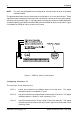


4 Introduction
StorCase Technology, Inc. DE90i-A User's Guide - Rev. B02
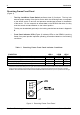
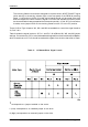
Table 1: Receiving Frame Front Panel Indicator Conditions
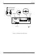
Figure 3: Receiving Frame Front Panel
CONDITION LED A LED B LED C
Carrier removed from receiving frame, power on ON OFF OFF
Carrier in receiving frame, unlocked position ON BLINK OFF
Carrier in receiving frame, locked position ON
(1)
ON
(1)
OFF
Drive activity active BLINK ON OFF
Invalid Master/Slave jumper configuration on J4A BLINK BLINK BLINK
(1)
Indicators A and B will alternately blink during the 10 second drive spin down/up period after the key has been turned on or off.
When the carrier has been unlocked from the receiving frame, these lights will flash as the drive spins down. DO NOT
REMOVE THE CARRIER FROM THE RECEIVING FRAME DURING THIS PERIOD to prevent possible drive damage.
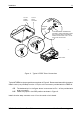
ReceivingFrameFrontPanel
(Figure 3)
The Key Lock/Drive Power Switch performs three (3) functions. The key lock
assures proper seating of the device carrier within the receiving frame, turns power
to the device carrier on and off, and prevents unauthorized removal or installation
of the carrier. For the computer to access data on the DE90i-A disk drive, the key
must be turned counterclockwise to the locked position.
The key can be attached (optional) to the locking mechanism as shown in Appendix
B.
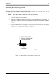
Front Panel Indicator LEDs (Figure 2) Indicator LEDs on the DE90i-A receiving
frame front panel provide important operating information based on the following
conditions: