StorCase® Technology Data Express® DE75i-SW Removable SCSI Wide Single-Ended Drive Enclosure User's Guide
i StorCase® Technology Data Express® DE75i-SW Removable SCSI Wide Single-Ended Drive Enclosure User's Guide Part No. D89-0000-0056 A01 December 2002 StorCaseTechnology, Inc. 17600 Newhope Street Fountain Valley, CA 92708-9885 Phone (714) 438-1850 Fax (714) 438-1847 DE75i-SW User's Guide - Rev. A01 StorCase Technology, Inc.
ii LIMITED WARRANTY STORCASE TECHNOLOGY, Incorporated (StorCase) warrants that its products will be free from defects in material and workmanship, subject to the conditions and limitations set forth below. StorCase will, at its option, either repair or replace any part of its product that proves defective by reason of improper workmanship or materials.
iii Free Technical Support StorCase provides free technical support. If you experience any difficulty during the installation or subsequent use of a StorCase product, please contact StorCases Technical Support Department prior to servicing your system. This warranty covers only repair or replacement of defective StorCase products, as described above. StorCase is not liable for, and does not cover under warranty, any costs associated with servicing and/or installation of StorCase products.
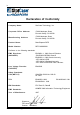
iv Declaration of Conformity Company Name: StorCase Technology, Inc.
v Table of Contents INTRODUCTION ..................................................................................................................... Packaging Information .................................................................................................. Serial Numbers .............................................................................................................. Package Contents ................................................................................................
vi List of Figures Figure 1: Figure 2: Figure 3: Figure 4: Figure 5: Figure 6: Figure 7: Figure 8: Figure 9: Figure 10: Package Contents .............................................................................................. 2 DE75i-SW Receiving Frame and Carrier ........................................................... 3 Receiving Frame Front Panel ............................................................................. 4 Receiving Frame Unit ID Number and Activity Display .................
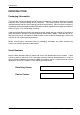
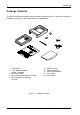
Introduction 1 INTRODUCTION Packaging Information The StorCase Technology Data Express® system is shipped in a container designed to provide protection and prevent damage during shipment. The Data Express unit was carefully inspected before and during the packing procedure at the factory. Bent or broken connectors, or evidence of other damage to the Data Express should be reported to the shipper immediately. Refer to Figure 1 for the package contents.
2 Introduction Package Contents The DE75i-SW product shipment should include the following items. If any item is missing or damaged, contact your StorCase dealer for a replacement. 3 2 4 1 5 7 6 8 Da I/O ID Driv e Carr Sele ier Disk (Not Driv Inclu e ded Pow ) er Cab le le ta E xpr ess Cab Cov (Pro er le vide d) Cab ct Cab le Driv Hard e Phil 3/16 lips wareMounting Flat # 6-32(4ea HD x ) 9 0151 Cab Scre le # Flat 6-32 ws (2Cover HD x 3/16plcs ) 10 0561d 1. Drive Carrier 2. 5.
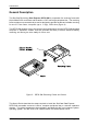
Introduction 3 General Description The StorCaseTechnology Data Express® DE75i-SW is composed of a receiving frame with 68-pin Wide SCSI connectors and fits within a 5.25" half-height peripheral slot. The receiving frame contains one removable drive carrier designed to provide durable and reliable mounting for one 3.5" form factor, low-profile (up to 1" high), SCSI drive (Figure 2).
4 Introduction Receiving Frame Front Panel (Figure 3) Key Lock/Drive Power Switch (Figure 3) - This key switch assures proper seating of the drive carrier within the receiving frame, turns power to the drive carrier on and off, and prevents unauthorized removal or installation of the carrier. For the computer to access data on the DE75i-SW drive, the key must be turned counterclockwise to the locked position. The key can be configured as either fixed or removable as shown in Appendix C.
Introduction 5 Figure 4: Receiving Frame Unit ID Number and Activity Display DE75i-SW User's Guide - Rev. A01 StorCase Technology, Inc.
6 Introduction Receiving Frame Rear Panel (Figure 5) I/O Connector - These connectors provide a standard interface for all SCSI signals (Figure 5). See Table 2 for pin assignments. DC Power Connector (J1) - A standard 4-pin DC power connector is used to accept DC power. Option Pins Remote Unit ID Selection - Pins 1-8 of this connector provide unit SCSI ID selection for the computer system or expansion chassis.
Installation 7 INSTALLATION Installing the Drive into the Carrier Preparation While performing the steps in this section, work on a soft surface to prevent excessive shock to the drive being installed. Also refer to the manufacturer's documentation provided with the drive. NOTE: A #2 Phillips screwdriver will be required during this procedure. 1. Remove the drive from its protective packaging. 2. Plastic Drive Bezel: If the drive to install is equipped with a plastic front bezel, remove it. 3.
8 Installation Installation 1. Attach the I/O cable from the DE75i-SW carrier board to the drive (Figure 6). 2. Attach the 4-pin power cable from the carrier board to the drive (Figure 6). 3. Install the 5-pin ID select cable into the carrier board connector (Figure 7). 4. Carefully insert the drive into the carrier at an angle, cable-end first. Make sure that none of the cables are pinched. Lower the front of the drive carefully into place.
Installation 9 TYPICAL 2MM DRIVE ID PIN CONFIGURATION Figure 7 illustrates a typical SCSI ID select connection to a drive with 2mm ID select pins. In most cases, the drive manufacturer labels each pair of SCSI ID select pins in their significant bit order (0, 1, 2, 3 as shown in Figure 7). In other cases, the manufacturer does not label these pins in their significant bit order, but instead, assigns pin numbers only. In any case, all odd numbered pins or all even numbered pins will be the signal row.
10 Installation Installing the Receiving Frame The drive should be installed into the carrier before installing the receiving frame into the mounting bay of a computer or expansion chassis. NOTE: Use a #2 Phillips screwdriver during this procedure. 1. Turn OFF power to the computer. 2. Open the computer system according to the manufacturers instructions. If necessary, temporarily remove any expansion boards that may make installation difficult. 3.
Installation 11 Table 1: Option Pin Signal Descriptions PIN Signal Function 1 2 3 4 5 6 7 8 9 10 11 12 13 14 15 16 17 18 19 20 21 22 ID0 GND ID1 GND ID2 GND ID3 GND DT GND RLEDC RLEDA DFAULT GND SYNC GND TPWR GND WTP GND LKA LKB SCSI ID Ground SCSI ID Ground SCSI ID Ground SCSI ID Ground Disable On Board Terminator Ground Remote LED Cathode Remote LED Anode Force Drive Fault Signal to Display Ground Drive Synchronization Signal Ground Terminate Power To/From SCSI Bus Ground Reserved Ground Disable I
12 Installation 4. With the drive carrier locked into place inside the receiving frame, install the DE75i-SW receiving frame into the drive opening in the computer or expansion chassis. Use the appropriate guides to position the DE75i-SW, and fasten it into place with four (4) #6-32 Phillips screws provided. Figure 9 illustrates the location of the mounting holes. Mounting holes are provided on each side and the bottom of the receiving frame to accommodate a variety of mounting configurations.
Installation 13 10. Replace any expansion boards that may have been removed earlier. Replace the system cover according to the manufacturers instructions. 11. Reconnect any system or peripheral cables removed earlier. 12. If the DE75i-SW has been installed into an external expansion chassis, connect the SCSI and power cables to the chassis. If the expansion chassis is at the end of a daisy chain, make certain that it is properly terminated.
14 Installation WARNING: Unlocking the carrier unit switches DC power OFF to the drive. Since drives require a short amount of time to spin down, allow at least 15 seconds before pulling the carrier unit out of the receiving frame to avoid possible damage to the drive. 3. A "u" will be displayed once the drive has completed spin down and is ready to be removed from the receiving frame. The indicator will return to the SCSI ID number when the carrier is removed from the receiving frame. 4.
Installation 15 SCSI Interface Connector The SCSI interface connector pin assignments are supplied for your convenience.
16 Appendix A - Specifications/Dimensions APPENDICES StorCase Technology, Inc. DE75i-SW User's Guide - Rev.
Appendix A - Specifications/Dimensions 17 Appendix A - Specifications/Dimensions SCSI Data Express subsystems conform to the Small Computer Systems Interface (SCSI) Standard set by the American National Standards Institute (ANSI).
18 Appendix A - Specifications/Dimensions Figure A-1: DE75i-SW Physical Dimensions (Dimensions are for reference only) StorCase Technology, Inc. DE75i-SW User's Guide - Rev.
Appendix B - Factory-Installed Options 19 Appendix B - Factory-Installed Options Hot Swap Board The DE75 SCSI Hot Swap Board allows the installation, removal or exchange of DE75i-SW carriers while your computer system is operating by monitoring and protecting the computer system and other peripheral devices on the SCSI Bus. The Hot Swap option eliminates the need to shut down your system when adding or removing a SCSI device by performing two functions: 1.
20 Appendix B - Factory-Installed Options Figure B-1: Attaching the Hot Swap Board Jumper Options Most jumper options are configurable via the receiving frame motherboard (Figure 7). The Hot Swap Board provides one configurable jumper, JP1 (Figure B-2). When installed (factory default), this jumper disables onboard termination. If the DE75i-SW is physically located at the end of a SCSI daisy chain, remove this jumper to enable termination.
Appendix B - Factory-Installed Options 21 Figure B-2: Hot Swap Board Termination Jumper WARNING: Be careful not to remove or disturb the carrier unit at this point. Although the carrier is physically unlocked, the drive requires a minimum of 15 seconds to spin down and is subject to vibration and possible damage during this period. 3. As the unit number flashes, the Hot Swap Board monitors the activity of the SCSI bus.
22 Appendix B - Factory-Installed Options NOTE: The timer for device spin down is controlled by a small selector, located in a cutout on the side of the DE75i-SW receiving frame as shown in Figure B-3. When the key is turned to the OFF position, and when the timer receives a "No SCSI Activity" signal from the Hot Swap Board, it waits the specified delay time before displaying a u on the front panel of the receiving frame.
Appendix C - Attaching the ON/OFF Key 23 Appendix C - Attaching the ON/OFF Key The following information will provide the necessary steps to attach the ON/OFF key to the key lock mechanism so that it is non-removable, preventing accidental key loss. The procedure can be reversed at a later date to revert back to a removable key. 1. Make certain power is OFF to the receiving frame. Locate the rectangular shaped key lock mechanism access hole on the inside of the receiving frame.
24 Appendix D - Optional Accessories Appendix D - Optional Accessories Carrying Case Figure D-1: Carrying Case The optional molded plastic carrying case is designed to transport the DE75i-SW carrier from one location to another in a safe, impact and moisture resistant environment. Its compact dimensions, 7 long x 9 wide x 3.5 high, make it easy to carry and to store.
Reader's Comments 25 Reader's Comments Please take a few moments when your computer system is up and running to send us your ideas and suggestions for improving our products and documentation.
Reader's Comments CUT ALONG THIS LINE FROM BOTTOM TO TOP OF PAGE 26 FOLD ALONG THIS LINE AND STAPLE SHUT NO POSTAGE NECESSARY IF MAILED IN THE UNITED STATES B U S I N E S S R E P LY M A I L FIRST CLASS MAIL PERMIT NO. 10686 SANTA ANA, CA POSTAGE WILL BE PAID BY ADDRESSEE TECHNOLOGY CORPORATION 17600 NEWHOPE STREET FOUNTAIN VALLEY CA 92708-9885 StorCase Technology, Inc. DE75i-SW User's Guide - Rev.