
Manual


12 Installation
StorCase Technology, Inc. DE75i-A User's Guide - Rev. C01
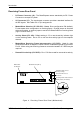
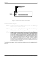
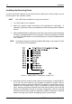
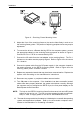
Figure 8: Master/Slave Configuration Jumper JP1
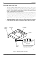
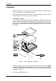
4. With the drive carrier locked in place inside the receiving frame, install the DE75i-
A into the 5.25 drive opening in the computer or expansion chassis. Use the
appropriate guides to position the DE75i-A, and fasten it into place with the four
(4) #6-32 x 1/4 screws provided. Figure 9 illustrates the location of the mounting
holes. Mounting holes are provided on each side and the bottom of the receiving
frame to accommodate a variety of mounting configurations. Use the mounting
holes which best suit the computer or expansion chassis configuration. Note that
bottom mounting holes require self-tapping screws (not provided).
InstallingtheReceivingFrame
The drive should be installed into the carrier before installing the receiving frame into the
mounting bay of the computer chassis.
NOTE: Use a #2 Phillips screwdriver during this procedure.
1. Turn OFF power to the computer.
2. Open the computer system according to the manufacturers instructions. If
necessary, temporarily remove any expansion boards that may make installation
difficult.
3. Select the Master/Slave configuration on the rear of the receiving frame by placing
a jumper on the appropriate (JP1) pins (Figure 8). Remove the jumper if you wish
to use the Unit Select switch on the receiving frame to configure the Master/Slave
drive selection.
NOTE: If using drive jumpers to determine Master/Slave status, set jumper JP1 ID0/
ID1 to match drive configuration.