
Manual


DE75i-A User's Guide - Rev. C01 StorCase Technology, Inc.
Installation 9
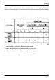
Table 2: J3 Master (No Slave) Signal Levels
* corresponds to a jumper installed on the carrier
L (Low) corresponds to an installed jumper on the drive
H (High) corresponds to a removed jumper on the drive.
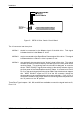
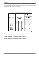
If a slave drive is removed, Table 3 shows the signal levels on J3 Pin 1 and Pin 2 that will result
for different W1, W2, and W3 jumper settings.