
User guide

DE100i-SWC160 User's Guide - Rev. D01 StorCase Technology, Inc.
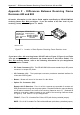
Appendix F - Differences Between Receiving Frame Revisions A00 and B00 29
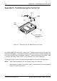
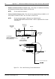
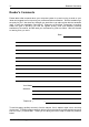
Figure F-3: Rev. A00 Receiving Frame Motherboard Option Pin Connector (W1)
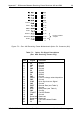
1 ID0 SCSI ID
2 GND Ground
3 ID1 SCSI ID
4 GND Ground
5 ID2 SCSI ID
6 GND Ground
7 ID3 SCSI ID
8 GND Ground
9 PULLS Force to change solenoid position
10 GND Ground
11 SYNC Drive Synchronous Signal
12 GND Ground
13 RMST Remote Start (see Table 3)
14 GND Ground
15 DYST Delay Start (see Table 3)
16 GND Ground
17 FFAULT Fan LED Enable
18 GND Ground
19 Reserved Reserved
20 Reserved Reserved
21 BUZZ Fan Failure Alarm Enable
22 5V 5V
PIN Signal Function
Table F-1: Option Pin Signal Descriptions
(Rev. A00 Receiving Frame Only)
Pin 10
Pin 12
Pin 14
Pin 22
Pin 20
Pin 18
Pin 16
0439d
SYNC
RMST
DYST
PULLS
FFAULT
BUZZ
Factory-Installed
Jumpers
Reserved
5V