StorCase® Technology Data Express® DE100i-SW DE100i-SWC Removable SCSI Wide Single-Ended Drive Enclosures User's Guide
i StorCase® Technology Data Express® DE100i-SW DE100i-SWC Removable SCSI Wide Single-Ended Drive Enclosures User's Guide Part No. D89-0000-0016 G01 January 2003 StorCase Technology, Inc. 17600 Newhope Street Fountain Valley, CA 92708-9885 Phone (714) 438-1850 Fax (714) 438-1847 DE100i-SW/SWC User's Guide - Rev. G01 StorCase Technology, Inc.
ii LIMITED WARRANTY STORCASE TECHNOLOGY, Incorporated (StorCase) warrants that its products will be free from defects in material and workmanship, subject to the conditions and limitations set forth below. StorCase will, at its option, either repair or replace any part of its product that proves defective by reason of improper workmanship or materials.
iii DE100i-SW/SWC User's Guide - Rev. G01 StorCase Technology, Inc.
iv Declaration of Conformity Company Name: StorCase Technology, Inc.
v Table of Contents INTRODUCTION ........................................................................................................................ Packaging Information ................................................................................................... Serial Numbers ............................................................................................................... Package Content ...........................................................................................
vi List of Figures Figure 1: Figure 2: Figure 3: Figure 4: Figure 5: Figure 6A: Figure 6B: Figure 7: Figure 8: Figure 9: Figure 10: Figure 11: Package Contents ............................................................................................... 2 DE100 Receiving Frame and Carrier .................................................................. 3 Receiving Frame Front Panel ..............................................................................
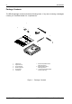
Introduction 1 INTRODUCTION Packaging Information The StorCase Technology Data Express® system is shipped in a container designed to provide protection and prevent damage during shipment. The Data Express unit was carefully inspected before and during the packing procedure at the factory. Bent or broken connectors, or evidence of other damage to the Data Express should be reported to the shipper immediately. Refer to Figure 1 for the package contents.
2 Introduction Package Contents The DE100 package contents include the following items. If any item is missing or damaged, contact your StorCase dealer for a replacement. 1 9 2 8 7 3 6 4 Da ta E xpr ess Driv e Carr ier 5 1. 2. 3. 4. 5. 6. Cable Cover Alignment Tool Drive Lock Keys Receiving Frame Drive Carrier Insert Sheet 7. #6-32 Phillips Machine Hd. Mounting Screws 8. #6-32 Phillips Flat Hd. Mounting Screws 9. 1.
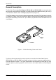
Introduction 3 General Description The StorCase Technology Data Express® DE100i-SW and DE100i-SWC are removable drive carriers and receiving frames designed to provide durable and reliable mounting for one (1) 3.5 SCSI drive within a 5.25" half-height peripheral slot (Figure 2). The DE100 allows a drive to be removed and transported to another DE100-equipped computer or expansion chassis, and also provides the ability to secure sensitive data by removing and storing the drive safely for future use.
4 Introduction Receiving Frame Front Panel The Key Lock/Drive Power Switch performs three (3) functions. The key lock assures proper seating of the drive carrier within the receiving frame, turns power to the drive carrier on and off, and prevents unauthorized removal or installation of the carrier. For the computer to access data on the DE100 disk drive, the key must be turned counterclockwise to the locked position.
Introduction 5 Figure 4: Receiving Frame Unit ID Number and Activity Display Receiving Frame Rear Panel I/O Connector (J2): The input/output connector provides a standard interface for all SCSI signals. DC Power Connector (J3): The DE100 uses a standard 4-pin DC Power Connector to accept DC power. ID Select Pins (J4): Pins 1-14 are reserved. Pins 15-20 of this connector provide unit SCSI ID selection for the computer system or expansion chassis.
6 Installation INSTALLATION Installing the Drive into the Carrier Preparation While performing the steps in this section, work on a soft surface to prevent excessive shock to the drive being installed. Also refer to the manufacturer's documentation provided with the drive. NOTE: A #2 Phillips screwdriver will be required during this procedure. 1. Remove the drive from its protective packaging. 2. Plastic Drive Bezel: If the drive came equipped with a plastic front bezel, it must be removed. 3.
Installation 7 Installation (DE100i-SW only) 1. Attach the I/O cable from the rear distribution board of the DE100i-SW carrier to the disk drive (Figure 6A). 2. Attach the 4-pin DC power cable from the rear distribution board to the disk drive (Figure 6A). 3. Install the 5-pin ID select cable into the rear signal distribution board connector. Refer to Figure 7 for a typical 2mm drive pin connection. 4. Carefully insert the drive into the carrier at an angle, cable-end first.
8 Installation Installation (DE100i-SWC only) 1. Attach the I/O cable from the rear distribution board of the DE100i-SWC carrier to the disk drive (Figure 6B). 2. Carefully insert the drive into the carrier at an angle, cable-end first. Make sure not to pinch the cable. Lower the front of the drive carefully into place. Fasten the drive into the carrier with four (4) #6-32 Phillips Flat Hd. screws provided. 5. Attach the provided cable cover with two (2) #6-32 Phillips Flat Hd. screws.
Installation 9 TYPICAL 2MM DRIVE ID PIN CONFIGURATION NOTE: Applies to the DE100i-SW only. Figure 7 illustrates a typical SCSI ID select connection to a drive with 2mm ID select pins. The wires on the wire harness connect to the positive pin (or signal pins) on the disk drive. In some cases, the drive manufacturer will label the signal pins as Pin 1, 3, 5, 7, (instead of 0, 1, 2, 3 as shown in Figure 7 below). Also, in some cases, the even-numbered Pins 2, 4, 6 are used for Ground.
10 Installation Figure 8: Receiving Frame Connector J4 Pin Configuration StorCase Technology, Inc. DE100i-SW/SWC User's Guide - Rev.
Installation 11 IMPORTANT NOTE: In order to use remote ID selection from a computer or expansion chassis, the Unit ID number on the DE100 receiving frame must be set to "0" with the provided alignment tool. Refer to the section "Selecting the Unit ID Number" later in this manual for the Unit ID selection procedure. 4. With the drive carrier locked in place inside the receiving frame, install the DE100 into the 5.25 drive opening in the computer or expansion chassis.
12 Installation 8. Connect the power cable from the DC power supply in the computer or expansion chassis to the power connector on the DE100 receiving frame. Refer to Figure 5 for the DE100 receiving frame power connector location. 9. Replace any expansion boards that may have been removed earlier. Replace the system cover according to the manufacturers instructions. 10. Reconnect any system or peripheral cables removed earlier. 11. Turn ON power to the computer.
Installation 13 NOTE: 5. The lock on the DE100 receiving frame serves two functions: 1) as a lock to secure the drive; and 2) as a DC power switch for the carrier unit. The lock must be engaged (turned counterclockwise) in order to supply power to the drive carrier. The new drive may need to be formatted or initialized prior to use with the operating system and applications software. Refer to the drive and/or computer manufacturer's documentation for formatting information.
14 Installation Adjusting the Spin Down/Up Timer NOTE: The timer for device spin down is controlled by a small selector, located in a cutout on the side of the DE100 receiving frame as shown in Figure 11. When the key is turned to the OFF position, and when the timer receives a No SCSI Activity signal from the Hot Swap Board, it waits the specified delay time before displaying a u on the front panel of the receiving frame.
Appendix A - Specifications/Dimensions 15 APPENDICES DE100i-SW/SWC User's Guide - Rev.G01 StorCase Technology, Inc.
16 Appendix A - Specifications/Dimensions Appendix A - Specifications/Dimensions SCSI Data Express subsystems conform to the Small Computer Systems Interface (SCSI) Standard set by the American National Standards Institute (ANSI).
Appendix A - Specifications/Dimensions Receiving Frame with Carrier 2.06 (52.3mm) 17 3.13 (79.5mm) 0.50 (12.7mm) #6-32 x 8 0.38 (9.7mm) 1.70 (43.2mm) 5.75 (146.1mm) 8.18 (207.8mm) Isolator Board Isolator Board DE100 Board 5.50 (139.7mm) 0.25 (6.4mm) 3.13 (79.5mm) 0.15 (3.8mm) #6-32 x 4 Bottom 0.64 (16.3mm) Carrier Only 1.68 (42.7mm) 7.38 (187.5mm) 3.75 (95.3mm) 4.67 (118.6mm) 1.75 (44.5mm) 0.25 (6.
18 Appendix B - Factory-Installed Options Appendix B - Factory-Installed Options DE100 Hot Swap Board The DE100 SCSI Hot Swap Board (P/N DX100-SW/H) allows the installation, removal or exchange of DE100i-SW and DE100i-SWC carriers while your computer system is operating by monitoring and protecting the computer system and other peripheral devices on the SCSI Bus. The Hot Swap option eliminates the need to shut down your system when adding or removing a SCSI device by performing two functions: 1.
Appendix B - Factory-Installed Options 4. 19 Attach the Hot Swap Board to the receiving frame motherboard by using the two screws removed earlier and insert them through the Hot Swap Board into the standoffs. Figure B-1: Attaching the Hot Swap Board DE100i-SW/SWC User's Guide - Rev. G01 StorCase Technology, Inc.
20 Appendix B - Factory-Installed Options Carrier Removal Follow the procedures below to remove the DE100 carrier from the receiving frame equipped with the Hot Swap option. 1. Verify that the drive is not active. If the system is on a network, make certain other users are not accessing the target drive, then disable it from the network. Dismount the drive. 2. Turn the DE100 key lock mechanism (located on the front of the receiving frame), clockwise to the OFF position.
Appendix B - Factory-Installed Options 21 Jumper Options The jumpers on the Hot Swap Board are similar to those on the standard SCSI Data Express Motherboard. See Figure B-2 for the Hot Swap Board jumper options. Make sure the factory-installed jumper is attached to J4 - Pins 1 & 2. Figure B-2: Hot Swap Board Jumper Options DE100i-SW/SWC User's Guide - Rev. G01 StorCase Technology, Inc.
22 Appendix B - Factory-Installed Options Solenoid Drive Lock The factory installed solenoid option prevents premature removal of the carrier and drive unit until the target drive has fully spun down. For most disk drives, this period of time can range from 15-40 seconds, depending on the type of drive being used (e.g. Seagate Barracuda drives require up to 50 seconds). Refer to the drive manufacturer's documentation for specific drive information.
Appendix C - Attaching the ON/OFF Key DE100i-SW/SWC User's Guide - Rev. G01 23 StorCase Technology, Inc.
24 Appendix D - Optional Accessories Appendix D - Optional Accessories Carrying Case Drive Carrier DX100-DE-C Carrying Case 0014 Figure D-1: Carrying Case The optional molded plastic carrying case is designed to transport the DE100 carrier from one site to another in a safe, impact and moisture resistant environment. Its compact dimensions, 7 long x 9 wide x 3.5 high, make it easy to carry and to store. The foam lining is contoured to fit a single Data Express carrier.
Appendix D - Optional Accessories 25 Drive Cover 1 Slip Drive Cover Lip into Top Rear of Carrier. The Sides of the Cover Will Fit Between the Drive and the Carrier. Mounting Holes Must be Towards Rear of Carrier. 1 3 Slide Drive Cover Forward Making Certain Front Cover Lip is Inside Carrier. Fasten Screws. 2 Drive Cover 3 2 Swing Drive Cover Down, Covering the Drive. Make Certain You Do Not Damage Connector Pins or Cables.
26 Appendix D - Optional Accessories Drive Plug 0429 Figure D-3: Drive Plug The drive plug (P/N DX100-PLUG), is designed to fill system or external enclosure bays that are occupied by receiving frames that have no carrier units installed. The purpose of the plug is to provide an attractive and functional method of directing proper air flow to the other installed devices in the system or external enclosure. StorCase Technology, Inc. DE100i-SW/SWC User's Guide - Rev.
Reader's Comments 27 Reader's Comments Please take a few moments when your computer system is up and running to send us your ideas and suggestions for improving our products and documentation.
Reader's Comments CUT ALONG THIS LINE FROM BOTTOM TO TOP OF PAGE 28 FOLD ALONG THIS LINE AND STAPLE SHUT NO POSTAGE NECESSARY IF MAILED IN THE UNITED STATES B U S I N E S S R E P LY M A I L FIRST CLASS MAIL PERMIT NO. 10686 SANTA ANA, CA POSTAGE WILL BE PAID BY ADDRESSEE TECHNOLOGY CORPORATION 17600 NEWHOPE STREET FOUNTAIN VALLEY CA 92708-9885 StorCase Technology, Inc. DE100i-SW/SWC User's Guide - Rev.