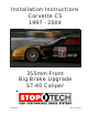
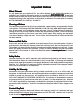
Installation Instructions Corvette C5 1997 - 2004 355mm Front Big Brake Upgrade ST-40 Caliper 98-180-1470 Rev.
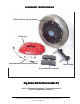
COMPONENT IDENTIFICA TION IDENTIFICATION 355mm AeroRotor and Hat Assembly ST-40 Caliper Stainless Braided Brake Line and Hardware Caliper Bracket High-Performance Street Pads Big B rake K it for the Cor Brake Kit Corvvette C5 (This is a representative photograph. The actual components in your kit may appear slightly different.) 3541 Unit A, Lomita Boulevard, Torrance, CA 90505 (310) 325-4799 www.stoptech.
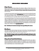
APPLICA TION DISCL AIMER APPLICATION DISCLAIMER Caliper Clearance Most 17” wheels will clear the outer diameter of the caliper for a 328mm or 332mm rotor kit. For a 355mm kit, a minimum 18” wheel is typically required, and for a 380mm rotor kit, a minimum 19” wheel is needed. The more critical clearance, however, is the gap between the spokes of the wheel and the face of the caliper. Do not assume that a larger-diameter wheel will automatically clear the face of the caliper.
APPLICA TION DISCL AIMER (Cont APPLICATION DISCLAIMER (Cont’’d.) Brake N oise Noise Certain brake pad compounds make more noise than others. Proper anti-squeal shim plates between the caliper pistons and backing plate of the pad help to reduce the problem. Anti-squeal lubricants are also available, to reduce some of the noise. The reality is that performance pads are more prone to brake squeal. Note: The customer is responsible for any squeal-related problems due to pad selection.
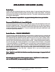
Impor tant N otices mportant Notices Wheel Fitment Do not assume that your wheels will fit. An outline drawing of your StopTech Big Brake kit is .stoptech.com available in the ‘Technical Information’ section of our website at www www.stoptech.com .stoptech.com. Measure the distance from the outer face of your stock caliper to the inner face of your wheel spokes, or make a template according to the instructions on the website, to determine if a wheel spacer is necessary.
Cor it Corvvette C5 F Frront Axle K Kit Note: It is important to read and understand this ENTIRE installation manual, including the bed-in procedure, before starting the installation.
Step 1 R aise Vehicle, and R emo Remo emovve Wheels Note: All photographs show a right-hand side installation, unless otherwise noted. A level, stable and clean surface, suitable for supporting the vehicle on jack-stands, should be used for the installation. War ning: N ev er leav ehicle suppor ted arning: Nev ever leavee any vvehicle supported with only a jack. Always use jack-stands.
Step 2 Disconnect Stock Brake Line War ning: B faces. IImmediately mmediately clean spilled br ake arning: Brrake fluid will damage most painted sur surfaces. brake fluid from any painted surface. Also be sure that the cap is securely installed on the master cylinder emo ake cylinder.. If the cap is loose or rremo emovv ed, it is likely that mor moree fluid will drip during br brake installation. Place a drip tray or several rags directly below the inboard brake line connection.
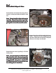
Step 3 Remo tock C aliper & R otor emovve SStock Caliper Rotor Remove the two stock caliper bolts, using a 21mm wrench or socket, and retain the bolts for later use. Note: F actor y-installed caliper bolts may be Factor actory-installed very tight. Ensure that you have a good purchase on the bolt head, and that you are in a good position to turn the wrench or socket. Remove the caliper with the stock brake line attached.
Step 4 Install Caliper Bracket Remove the Jet nuts and washers from the caliper mounting bracket, and put them aside for later use. Place a few drops of the supplied Loctite 262 on the threads of each stock caliper bolt. Install the caliper bracket, using the stock caliper mounting bolts, with the bracket mounted on the outboard side of the mounting lugs, and the bolts inserted from the inboard side.
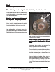
Step 5 Install AeroRotor Assembly AeroRotors MUST be cleaned with soap and water prior to installation. Not doing so will damage the rotors and pads, and will prevent the brakes from performing properly. Even though the rotors may look clean, the rust inhibitor is in place, and it must be removed. Not cleaning the rotors will severely impact the performance of your new brake system.
Step 5 (Cont (Cont’’d.) Install AeroRotor Assembly It may be necessary to clearance the lower ball joint slightly, to clear the inboard face of the AeroRotor during full suspension travel. A coarse file can remove the material, although a power grinder is more efficient, if used properly. Install the rotor, and check the proximity of the lower ball joint to the inner rotor face. Turn the wheel lock-to-lock, to determine how far around the front and back edge needs to be clearanced.
Left-Side Rotor Outboard Side Driv er river er’’s Left Right-Side Rotor Outboard Side Driv er river er’’s Right 3541 Unit A, Lomita Boulevard, Torrance, CA 90505 (310) 325-4799 www.stoptech.
3541 Unit A, Lomita Boulevard, Torrance, CA 90505 (310) 325-4799 www.stoptech.
Caliper Component IIdentification dentification Use a light film of anti-seize on the bridge bolt shafts and threads The ST-40 original equipment caliper uses a common Porsche-style pad. The Friction Materials Standards Institute (FMSI) number for the pad backing plate is D372. For further pad interchange information, please see the FAQ section of the StopTech website at: www.stoptech.com 3541 Unit A, Lomita Boulevard, Torrance, CA 90505 (310) 325-4799 www.stoptech.
Step 6 Install C aliper and P ads Caliper Pads Note: The images in this section may not be of the vvehicle ehicle noted, but the oper theyy giv givee a pr proper representation of the correct installation. Determine the left- and right-hand side calipers. They are clearly marked on the box, but as a check, the bleed screws are always positioned at the top of the caliper.
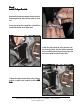
Step 6 (Cont (Cont’’d.) Install C aliper and P ads Caliper Pads Install the caliper onto the adapter bracket, orienting it so that the bleed screws are positioned on the top side of the caliper. Take care to ensure that the caliper is square and evenly started on both studs. It may be necessary to use a mallet to gently tap the caliper into position. Install a Jet nut onto each stud, with a 12mm washer under each nut. Tighten the Jet nuts to 40 lb-ft of torque, using a 1/2” wrench or socket.
Step 6 (Cont (Cont’’d.) Install C aliper and P ads Caliper Pads Install the bridge by sliding it into position, and rocking it until one of the bolt holes lines up. Take care to ensure that the bridge is slid straight and parallel into the caliper body opening. Note: The bridge is dir ectional, and should directional, be positioned so that the air-scoop opening is located in the bottom half of the bridge.
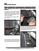
Step 7 Attach SStainless tainless SSteel teel B rake Line Brake Install the caliper end of the stainless steel brake line by first placing a copper crush washer on either side of the banjo fitting, then inserting the banjo bolt into the fitting. Copper Banjo bolt Insert the banjo bolt into the caliper, angling the banjo fitting so that it is leaning slightly forward. oximately 14 lbappro Torque the banjo bolt to appr ft, using a 14mm wrench or socket.
Step 7 (Cont (Cont’’d.) Attach SStainless tainless SSteel teel B rake Line Brake Reinstall the line-retaining spring clip, to secure the stainless brake line in place. Take care to ensure that the prongs on the spring clip are seated within the recesses on the brake line fitting, then use a mallet to gently tap the spring clip into place. After securing the brake line, turn the wheels lockto-lock to ensure that the line is not binding or touching any moving part of the suspension.
Step 8 Bleed Brakes Complete the installation on both sides of the vehicle before bleeding the system. Note: The calipers and lines will need to fill with fluid, quickly dr aining the master cylinder draining eep a close watch on the fluid lev el when initially bleeding the system. D w eservv oir oir.. K Keep level Doo not allo allow reser the master cylinder rreser eser un dr aw in air oing so may rresult esult in the br dryy, and to dr draw air..
Step 9 Reinstall Wheels It is very important to check the wheel-to-caliper clearance before installing wheels! Note: S ome wheels ar e-backed lead w Some aree balanced on the inside, with adhesiv adhesive-backed weights. eights. If the fer weight is on the outboar d edge, behind the spokes, it may inter outboard interfer feree with the caliper caliper..
AeroRotor Installation & Bed-in Procedure READ THIS NOW FAIL URE TO READ, UNDERST AND AND FOLL OW THESE PR OCEDURES AILURE UNDERSTAND FOLLO PROCEDURES WILL CA USE P ERMANENT DAMA GE TO YOUR BRAKE R OTORS, AND WILL RO CAUSE PERMANENT DAMAGE KEEP THE SYSTEM FR OM WORKING A T IT S FULL CAP ACIT Y. CITY FROM AT ITS CAPA The majority of brake system problems are due to improper installation and/or bed-in of the rotors and pads.
Rotor and P ad Bed-in (Cont Pad (Cont’’d.) Note: B edding-in of pads should not be done in poor w eather conditions, nor on w et rroads. oads. Bedding-in weather wet After completing the installation, make a series of 10 stops from 60 to 5-10 MPH. At the end of each stop, immediately accelerate to 60 again for the next stop. Run all stops in one cycle. During the 60 to 5-10 MPH cycle of stops, the exact speed is not critical. Accelerate to approximately 60, then begin braking.
Thank yyou ou for selecting SStopT topT ech. topTech. We realize that you had a choice when selecting a big brake upgrade for your vehicle, and we know that you’ll be happy with our system. We proudly support our fine products. For any assistance or questions, please contact our Customer Service Department at (310) 325-4799 - extension 105 or e-mail us at support@stoptech.