
User manual
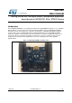
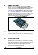

Hardware description
UM1900
8/15
DocID027905 Rev 1
2-microphone acquisition
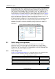
As previously mentioned, this is the case in which the I²S peripheral is used to generate
twice the frequency needed by the microphones. In this scenario, the clock is then halved
by the timer and routed to the microphones to give them the right clock. I²S therefore reads
values from both edges of the merged PDM lines. For this configuration you need the
following SB configuration:
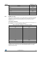
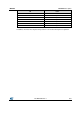
Table 3: Solder bridge configuration for 2-microphone acquisition
SB
Status
SB7
Close
SB8
Open
SB9
Open /Close
SB10
Open
SB11
Close
SB12
Open
SB13
Close
SB14
Open
SB15
Close
SB16
Open
SB17
Open
SB18
Open
SB19
Open
SB20
Open
SB21
Open
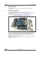
In addition, J2 is placed in position 1-2 for onboard microphone acquisition or 2-3 for using
external microphones, while J3 must is open. When acquiring onboard microphones, close
SB9 to acquire both of them.
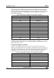
4-external-microphone acquisition
In this case, the I²S peripheral is used to generate a clock frequency that is twice the
frequency needed by the microphones, and SPI is configured in slave mode in order to use
such timing. As in the previous case, the clock is then halved by the timer and routed to the
microphones to give the right clock. I²S and SPI read values from both the edges of the
merged PDM lines. For this configuration you need the following SB configuration:
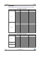
Table 4: Solder bridge configuration for 4-microphone acquisition
SB
Status
SB7
Close
SB8
Close
SB9
Open
SB10
Close
SB11
Close
SB12
Open
SB13
Close
SB14
Open