
User manual

UM1900
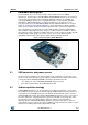
Hardware description
DocID027905 Rev 1
7/15
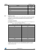
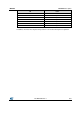
Function
Solder bridge
Merges onboard microphone PDMs in order to be acquired with a single
interface
SB9
Connects MIC34 PDM to MCU SPI MOSI pin
SB10
Connects MIC12 PDM to MCU I²S SD pin
SB11
Reserved
SB12
I²S clock from MCU
SB13
Connects I²S clock directly to MIC clock without passing through timer
SB14
Connect I²S clock to MCU timer input channel
SB15
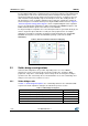
3.3.2 Sample use cases
In this section, we analyze specific use cases together with the corresponding solder bridge
configurations. Custom setups are also possible for ad-hoc functionalities. Note that SB1,
SB2, SB6 are reserved for the USB or Oscillator pins and are not part of the audio
acquisition process.
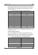
1-microphone acquisition
The I²S peripheral is used to directly acquire and give the right clock to the microphone. For
this configuration, you need the following SB configuration.
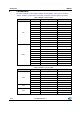
Table 2: Solder bridge configuration for 1 microphone acquisition
SB
Status
SB7
Open
SB8
Open
SB9
Open
SB10
Open
SB11
Close
SB12
Open
SB13
Close
SB14
Close
SB15
Open
SB16
Open
SB17
Open
SB18
Open
SB19
Open
SB20
Open
SB21
Open
In addition, J2 is placed in position 1-2 for onboard microphone acquisition or 2-3 for an
external microphone, while J3 is left open. If using external microphones, do not plug
anything in M2_EXT header.