
User manual

Connectors
UM1900
10/15
DocID027905 Rev 1
4 Connectors
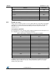
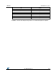
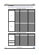
The pin assignments for the Arduino UNO R3 and the Morpho connectors are shown in
Table 6: "Arduino connector table" and Table 5: "Morpho connector table" respectively.
Table 5: Morpho connector table
Connector
Pin
Signal
Remarks
CN7
1
MIC_CLKx2
If SB20 is close
3
MIC_PDM34
If SB20 is close
6
E5V
12
3V3
16
3V3
18
5V
20
GND
22
GND
24
V_IN
29
OSC_CLK_OUT
If SB6 is close
35
MIC_CLK_NUCLEO
If SB12 is close
CN10
11
MIC_CLKx2
If SB8 is close
12
OTG_FS_DP_NUCLEO
If SB1 is close
14
OTG_FS_DM_NUCLEO
If SB2 is close
15
MIC_PDM34
If SB10 is close
25
MIC_PDM34
If SB17 is close
26
MIC_PDM12
If SB11 is close
27
MIC_CLKx2
If SB15 is close
28
MIC_PDM12
If SB16 is close
29
MIC_CLK_NUCLEO
If SB7 is close
30
MIC_CLKx2
If SB13 is close
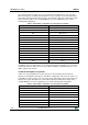
Table 6: Arduino connector table
Connector
Pin
Signal
Remarks
CN6
2
3V3
4
3V3
5
5V
6
GND
7
GND
8
V_IN
CN5
6
MIC_CLKx2
If SB8 is close
4
MIC_PDM34
If SB10 is close
CN9
7
MIC_PDM34
If SB17 is close
6
MIC_CLKx2
If SB15 is close
5
MIC_CLK_NUCLEO
If SB7 is close