
Data Sheet
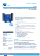
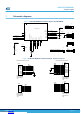
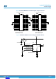
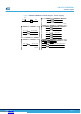

Figure 3. X-NUCLEO-BNRG2A1 schematic diagram - morpho connectors
PA6
PB2
PC5
19
38
22
PC14
15
23
13
25
37
CN10
12
PA0
+5V
4
26
PC11
PB0
24
PB7
PA2
PA11
PA7
VLCD/VBAT
5
3
5
PB14
7
PA15
NC
22
37
29
PA10
PC1
PB9
U5V
30
PC15
21
27
23
11
8
6
2
15
PA1
10
8
32
PC3
PC9
BOOT0
Pass-Through: Female on
Bottom and Male on Top
Pass-Through: Female on
Bottom and Male on Top
NC/PF5
PA12
27
PB6
AGND
20
VDD
PC2
1
3
PB15
36
38
+3V3
20
2
19
33
1
PA8
31
PC0
AVDD
PA13
PB3
34
PB11/NC
PD8
PC7
PH0/PF0/PD0
26 25
10
24
13
28
18
VIN
36
30
E5V
29
PB5
PB8
NC/PF4
PC8
PA5
PC4
PC12
16
18
12
CN10CN7
PB1
PC6
9
21
34
PC10
PC13
4
17 17
6
35
28
RESET
PA4
NC/PF7
CN7
PB10
ST morpho SX Connector
PA3
32
PB12
PA9
PH1/PF1/PD1
14
NC/PF6
7
PB13
9
PA14
11
35
14
IOREF
33
16
NC
PD2
31
PB4
ST morpho DX Connector
Figure 4. X-NUCLEO-BNRG2A1 schematic diagram - M95640-RMC6TG
3
VCC
U9
M95640-RMC6TG
R74
100K
SPI_CLK
8
C48
100nF,16V
GND
Ex_Pad
9
PB6_SPI_CSN
4
+3V3
PA6_SPI_MISO
/W
7
/HOLD
PA7_SPI_MOSI
/S
Q
R75
100K
1
2
C
6
D
5
X-NUCLEO-BNRG2A1
Schematic diagrams
DB4086 - Rev 1
page 6/9
Downloaded from Arrow.com.Downloaded from Arrow.com.Downloaded from Arrow.com.Downloaded from Arrow.com.Downloaded from Arrow.com.Downloaded from Arrow.com.