
Datasheet


Table Of Contents
- 1 Absolute maximum ratings and operating conditions
- 2 Electrical characteristics
- 3 Typical characteristics
- Figure 2. Supply current (each amplifier) versus supply voltage
- Figure 3. Input bias current versus free air temperature
- Figure 4. High level output voltage versus high level output current
- Figure 5. High level output voltage versus high level output current
- Figure 6. Low level output voltage versus low level output current
- Figure 7. Low level output voltage versus low level output current
- Figure 8. Open-loop frequency response and phase shift
- Figure 9. Gain bandwidth product versus supply voltage
- Figure 10. Phase margin versus supply voltage
- Figure 11. Phase margin versus capacitive load
- Figure 12. Slew rate versus supply voltage
- Figure 13. Input voltage noise versus frequency
- 4 Package information
- 5 Ordering information
- 6 Revision history
Package information TS27M2, TS27M2A, TS27M2B
10/14 Doc ID 2306 Rev 2
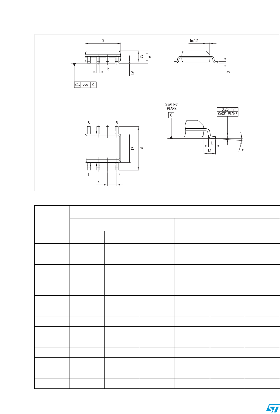
4.2 SO-8 package information
Figure 15. SO-8 package mechanical drawing
Table 5. SO-8 package mechanical data
Ref.
Dimensions
Millimeters Inches
Min. Typ. Max. Min. Typ. Max.
A1.750.069
A1 0.10 0.25 0.004 0.010
A2 1.25 0.049
b 0.28 0.48 0.011 0.019
c 0.17 0.23 0.007 0.010
D 4.80 4.90 5.00 0.189 0.193 0.197
E 5.80 6.00 6.20 0.228 0.236 0.244
E1 3.80 3.90 4.00 0.150 0.154 0.157
e 1.27 0.050
h 0.25 0.50 0.010 0.020
L 0.40 1.27 0.016 0.050
L1 1.04 0.040
k1° 8°1° 8°
ccc 0.10 0.004