
Datasheet


Table Of Contents
- Table 1. Device summary
- 1 Characteristics
- Table 2. Absolute maximum ratings (Tamb = 25 °C)
- Table 3. Thermal resistances
- Figure 1. Electrical characteristics - definitions
- Table 4. Electrical characteristics - values
- Figure 2. Clamping voltage versus peak pulse current - STRVS118X02C (typical values)
- Figure 3. Clamping voltage versus peak pulse current - STRVS142X02F (typical values)
- Figure 4. Clamping voltage versus peak pulse current - STRVS182X02F (typical values)
- Figure 5. Clamping voltage versus peak pulse current - STRVS185X02B/E (typical values)
- Figure 6. Clamping voltage versus peak pulse current - STRVS222X02F (typical values)
- Figure 7. Clamping voltage versus peak pulse current - STRVS225X02E (typical values)
- Figure 8. Clamping voltage versus peak pulse current - STRVS241X02E (typical values)
- Figure 9. Clamping voltage versus peak pulse current - STRVS248X02C (typical values)
- Figure 10. Clamping voltage versus peak pulse current - STRVS252X02F
- Figure 11. Clamping voltage versus peak pulse current - STRVS280X02F
- Figure 12. Leakage current versus junction temperature (typical values) STRVSxxxC
- Figure 13. Leakage current versus junction temperature (typical values) STRVSxxxF
- Figure 14. Leakage current versus junction temperature (typical values) STRVSxxxB
- Figure 15. Leakage current versus junction temperature (typical values) STRVSxxxE
- Figure 16. Thermal resistance junction to ambient versus copper surface of connections - SMB
- Figure 17. Thermal resistance junction to ambient versus copper surface of connections - SMC
- Figure 18. Thermal resistance junction to ambient versus copper surface of connections - DO-15
- Figure 19. Thermal resistance junction to ambient versus copper surface of connections - DO-201
- 2 Package information
- Figure 20. SMB dimension definitions
- Table 5. SMB dimension values
- Figure 21. SMB Footprint, dimensions in mm (inches)
- Figure 22. SMB marking layout
- Figure 23. SMC dimension definitions
- Table 6. SMC dimension values
- Figure 24. SMC footprint, dimensions in mm (inches)
- Figure 25. SMC marking layout
- Figure 26. DO-15 dimension definitions
- Table 7. DO-15 dimension values
- Figure 27. DO-201 dimension definitions
- Table 8. DO-201 dimension values
- 3 Ordering information
- 4 Revision history
DocID023950 Rev 3 3/13
STRVSX Characteristics
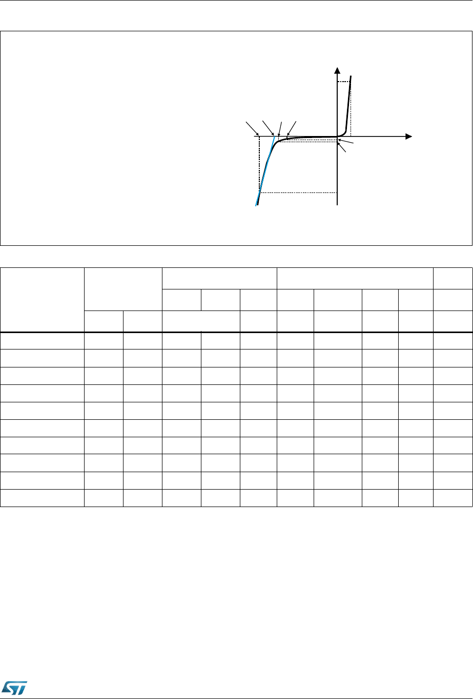
Figure 1. Electrical characteristics - definitions
Symbol Parameter
V = Breakdown voltage
I = Leakage current @ V
V = Stand-off voltage
V
V
= Clamping voltage at I
PP
= Clamping voltage where R line
d
crosses current axis
I = Peak pulse current
BR
RM RM
RM
CL
CL0
PP
V
I
V
CL
V
V
BR
CL0
V
RM
I
F
V
F
I
I
RM
R
I
PP
Slope: V/I = R
d
I = Forward current
F
V = Forward voltage
F
R
αT
= Dynamic resistance
= Voltage temperature coefficient on V
BR
d
Table 4. Electrical characteristics - values
Order code
I
RM
max @ V
RM
(25 °C)
V
BR
@ I
R
(1)
(25 °C) Values @ 125 °C (typ.) αT
Min. Max. I
PP
V
CL
@ I
pp
V
CL0
R
d
(2)
Max.
µA V V mA A V V Ω 10
-4
/°C
STRVS118X02C 0.2 85 95 105 1 2 118 116 1.0 10.6
STRVS142X02F 1 102 114 126 1 2 142 140 1.0 10.7
STRVS182X02F 1 128 143 158 1 2 182 177 2.5 10.8
STRVS185X02B/E 0.2 128 143 158 1 2 185 178 2.5 10.8
STRVS222X02F 1 154 171 189 1 2 222 213 4.5 10.8
STRVS225X02E 0.5 154 171 189 1 2 225 214 5.5 10.8
STRVS241X02E 0.5 171 190 210 1 2 241 234 3.5 10.8
STRVS248X02C 0.5 171 190 210 1 2 248 238 5.0 10.8
STRVS252X02F 1 171 190 210 1 2 252 239 6.5 10.8
STRVS280X02F 1 188 209 231 1 2 280 263 8.5 10.8
1. To calculate V
BR
at a given junction temperature, use the following formula: V
BR
@ T
j
= V
BR
@ 25 °C x (1 +
αT x (T
j
- 25))
2. R
d
= (V
CL
- V
CL0
)/I
PP