
Datasheet


Table Of Contents
- Table 1. Device summary
- 1 Characteristics
- Table 2. Absolute maximum ratings (Tamb = 25 °C)
- Table 3. Thermal resistances
- Figure 1. Electrical characteristics - definitions
- Table 4. Electrical characteristics - values
- Figure 2. Clamping voltage versus peak pulse current - STRVS118X02C (typical values)
- Figure 3. Clamping voltage versus peak pulse current - STRVS142X02F (typical values)
- Figure 4. Clamping voltage versus peak pulse current - STRVS182X02F (typical values)
- Figure 5. Clamping voltage versus peak pulse current - STRVS185X02B/E (typical values)
- Figure 6. Clamping voltage versus peak pulse current - STRVS222X02F (typical values)
- Figure 7. Clamping voltage versus peak pulse current - STRVS225X02E (typical values)
- Figure 8. Clamping voltage versus peak pulse current - STRVS241X02E (typical values)
- Figure 9. Clamping voltage versus peak pulse current - STRVS248X02C (typical values)
- Figure 10. Clamping voltage versus peak pulse current - STRVS252X02F
- Figure 11. Clamping voltage versus peak pulse current - STRVS280X02F
- Figure 12. Leakage current versus junction temperature (typical values) STRVSxxxC
- Figure 13. Leakage current versus junction temperature (typical values) STRVSxxxF
- Figure 14. Leakage current versus junction temperature (typical values) STRVSxxxB
- Figure 15. Leakage current versus junction temperature (typical values) STRVSxxxE
- Figure 16. Thermal resistance junction to ambient versus copper surface of connections - SMB
- Figure 17. Thermal resistance junction to ambient versus copper surface of connections - SMC
- Figure 18. Thermal resistance junction to ambient versus copper surface of connections - DO-15
- Figure 19. Thermal resistance junction to ambient versus copper surface of connections - DO-201
- 2 Package information
- Figure 20. SMB dimension definitions
- Table 5. SMB dimension values
- Figure 21. SMB Footprint, dimensions in mm (inches)
- Figure 22. SMB marking layout
- Figure 23. SMC dimension definitions
- Table 6. SMC dimension values
- Figure 24. SMC footprint, dimensions in mm (inches)
- Figure 25. SMC marking layout
- Figure 26. DO-15 dimension definitions
- Table 7. DO-15 dimension values
- Figure 27. DO-201 dimension definitions
- Table 8. DO-201 dimension values
- 3 Ordering information
- 4 Revision history
Characteristics STRVSX
2/13 DocID023950 Rev 3
1 Characteristics
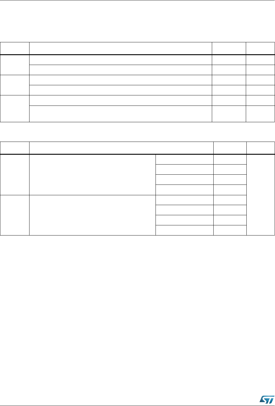
Table 2. Absolute maximum ratings (T
amb
= 25 °C)
Symbol Parameter Value Unit
T
j
Operating junction temperature range (SMB and SMC) -55 to 150 °C
Operating junction temperature range (DO-15 and DO-201) -55 to 175 °C
T
stg
Storage temperature range (SMB and SMC) -65 to 150 °C
Storage temperature range (DO-15 and DO-201) -65 to 175 °C
T
L
Maximum lead temperature for soldering during 10 s (SMB and SMC) 260 °C
Maximum lead temperature for soldering during 10 s at 5 mm from case
(DO-15 and DO-201)
260 °C
Table 3. Thermal resistances
Symbol Parameter Value Unit
R
th(j-l)
Junction to leads
SMB 13
°C/W
SMC 12
DO-15 35
DO-201 23
R
th(j-a)
Junction to ambient
(1)
SMB 185
SMC 150
DO-15 105
DO-201 100
1. On printed circuit with recommended pad layout