
Datasheet
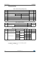
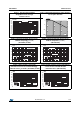
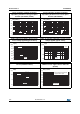
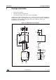
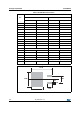
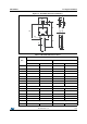
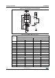
Table Of Contents
- Table 1. Device summary
- 1 Characteristics
- Table 2. Absolute ratings (limiting values)
- Table 3. Thermal resistance
- Table 4. Static electrical characteristics (per diode)
- Figure 1. Average forward power dissipation versus average forward current
- Figure 2. Normalized avalanche power derating versus pulse duration
- Figure 3. Average forward current versus ambient temperature, d = 0.5, (TO-220AC, D2PAK)
- Figure 4. Average forward current versus ambient temperature, d = 0.5, (TO-220FPAC)
- Figure 5. Non repetitive surge peak forward current versus overload duration - maximum values, per diode (TO-220AC, D2PAK)
- Figure 6. Non repetitive surge peak forward current versus overload duration - maximum values (TO-220FPAC)
- Figure 7. Relative variation of thermal impedance junction to case versus pulse duration (TO-220AC, D2PAK)
- Figure 8. Relative variation of thermal impedance junction to case versus pulse duration (TO-220FPAC)
- Figure 9. Reverse leakage current versus reverse voltage applied (typical values)
- Figure 10. Junction capacitance versus reverse voltage applied (typical values)
- Figure 11. Forward voltage drop versus forward current (maximum values)
- Figure 12. Thermal resistance junction to ambient versus copper surface under tab (D²PAK)
- 2 Package Information
- 3 Ordering Information
- 4 Revision history
DocID5387 Rev 11 5/10
STPS8H100 Package Information
10
2 Package Information
• Epoxy meets UL94,V0
• Cooling method: by conduction (C)
• Recommended torque value: 0.4 to 0.6 N·m (TO-220AC)
In order to meet environmental requirements, ST offers these devices in different grades of
ECOPACK
®
packages, depending on their level of environmental compliance. ECOPACK
®
specifications, grade definitions and product status are available at: www.st.com.
ECOPACK
®
is an ST trademark.
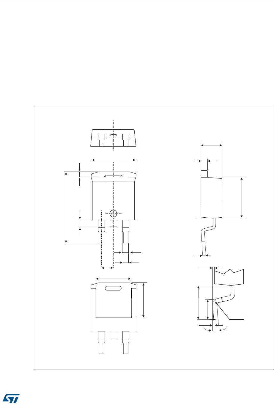
Figure 13. D
2
PAK dimension definitions
e
H
L2
L1
b
b2
E
E1
D1
A
C2
D
A1
0 - 8°
C
L4
L3
L
Gauge
plane