
Datasheet


Timing diagrams STP16CPP05
10/28 Doc ID 15379 Rev 2
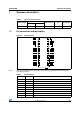
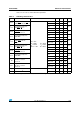
5 Timing diagrams
Note: OUTn = ON when Dn = H OUTn = OFF when Dn = L
Figure 7. Timing diagram
Note: The latches circuit holds data when the LE terminal is Low.
1 When LE terminal is at high level, latch circuit does not hold the data it passes from the input
to the output.
2 When OE
terminal is at low level, output terminals OUT0 to OUT15 respond to the data,
either ON or OFF.
3 When OE
terminal is at high level, it switches off all the data on the output terminal.
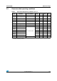
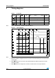
Table 9. Truth table
CLOCK LE OE
SERIAL-
IN
OUT0 ............. OUT7 ................ OUT15 SDO
H L Dn Dn ..... Dn - 7 ..... Dn -15 Dn - 15
L L Dn + 1 No change Dn - 14
H L Dn + 2 Dn + 2 ..... Dn - 5 ..... Dn -13 Dn - 13
X L Dn + 3 Dn + 2 ..... Dn - 5 ..... Dn -13 Dn - 13
X H Dn + 3 OFF Dn - 13