
Datasheet
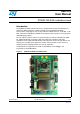

UM01018 Hardware and layout
Doc ID 18141 Rev 2 9/42
2.3 Clock source
Two clock sources are available on the STM32L152-EVAL evaluation board for the
STM32L152VBT6 and embedded RTC.
● X1, 32 KHz crystal for embedded RTC
● X2, 8 MHz crystal with socket for the STM32L152VBT6 microcontroller, it can be
removed from the socket when an internal RC clock is used.
2.4 Reset source
The reset signal of the STM32L152-EVAL evaluation board is low active and the reset
sources include:
● Reset button B1
● Debugging Tools from JTAG connector CN9 and trace connector CN8
● Daughterboard from CN7
● Embedded ST-LINK/V2
● RS-232 connector CN2 for ISP
Note: Jumper JP9 must be changed for RESET. This is handled by pin8 of the RS-232 connector
CN2 (CTS signal), refer to Section 2.9 for details.
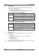
Table 2. 32 KHz crystal X1 related solder bridges
Solder bridge Description
SB1
PC14 is connected to 32 KHz crystal when SB1 is open (default setting).
PC14 is connected to extension connector CN6 when SB1 is closed. In such
case R37 must be removed to avoid disturbance due to the 32 KHz quartz.
SB4
PC15 is connected to 32 KHz crystal when SB4 is open (default setting).
PC15 is connected to extension connector CN6 when SB4 is closed. In such
case R38 must be removed to avoid disturbance due to the 32 KHz quartz.
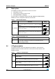
Table 3. 8 MHz crystal X2 related solder bridges
Solder bridge Description
SB2
PH1 is connected to 8 MHz crystal when SB2 is open (default setting).
PH1 is connected to extension connector CN7 when SB2 is closed. In such case
R39 must be removed to avoid disturbance due to the 8 MHz quartz.
SB3
PH0 is connected to 8 MHz crystal when SB3 is open (default setting).
PH1 is connected to extension connector CN7 when SB3 is closed. In such case
C30 and X2 must be removed.