
Datasheet

Hardware and layout UM01018
14/42 Doc ID 18141 Rev 2
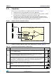
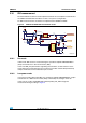
2.14 Temperature sensor
A temperature sensor STLM75M2E is connected to the I2C bus of the STM32L152VBT6
through two transistors to support a wide voltage range, from 1.65 V to 3.6 V.
2.15 Display and input devices
The display devices are:
● 2.4" color TFT LCD, connected to the SPI1 port of the STM32L152VBT6.
● 4 general purpose color LED's (LD 1,2,3,4).
LD3 and LD4 are disabled by default; JP18 and JP19 must be closed to enable these
two LEDs.
The input devices are:
● 4-direction joystick (U30) with selection key
● Wakeup button (B2)
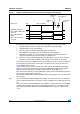
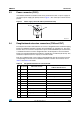
JP11
PB5 is connected to I2C_SMB, the interrupt output of temperature sensor U18 when JP11 is closed
(default setting).
PB5 is disconnected from I2C_SMB but remains connected to COM_IN+ when JP11 is open for
comparator application.
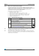
Table 10. Comparator and potentiometer related jumpers (continued)
Jumper Description Setting
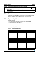
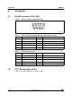
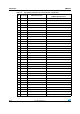
Table 11. 2.4" TFT LCD module CN14
Pin on CN3 Description Pin connection
1CS PH2
2SCL PE13
3SDI PE15
4RS -
5WR -
6RD -
7SDO PE14
8 RESET RESET#
9VDD 3.3V
10 VCI 3.3V
11 GND GND
12 GND GND
13 BL_VDD 5V
14 BL_Control 5V
15 BL_GND GND
16 BL_GND GND