
Datasheet

Electrical characteristics STM32L15xCC STM32L15xRC STM32L15xUC STM32L15xVC
98/132 DocID022799 Rev 6
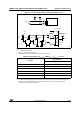
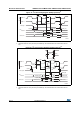
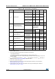
Figure 27. USB timings: definition of data signal rise and fall time
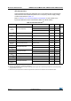
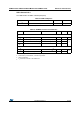
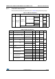
Table 54. USB: full speed electrical characteristics
Driver characteristics
(1)
1. Guaranteed by design, not tested in production.
Symbol Parameter Conditions Min Max Unit
t
r
Rise time
(2)
2.
Measured from 10% to 90% of the data signal. For more detailed informations, please refer to USB
Specification - Chapter 7 (version 2.0).
C
L
= 50 pF
420ns
t
f
Fall Time
(2)
C
L
= 50 pF 4 20 ns
t
rfm
Rise/ fall time matching t
r
/t
f
90 110 %
V
CRS
Output signal crossover voltage 1.3 2.0 V
ai14137
t
f
Differen tial
Data L ines
V
SS
V
CR S
t
r
Crossover
points