
Datasheet

Electrical characteristics STM32L15xCC STM32L15xRC STM32L15xUC STM32L15xVC
94/132 DocID022799 Rev 6
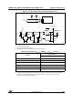
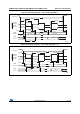
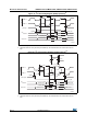
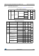
Figure 24. SPI timing diagram - master mode
(1)
1. Measurement points are done at CMOS levels: 0.3V
DD
and 0.7V
DD.
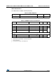
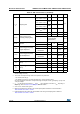
I2S characteristics
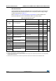
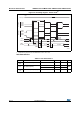
Table 51. I2S characteristics
Symbol Parameter Conditions Min Max Unit
f
MCK
I2S Main Clock Output 256 x 8K 256xFs
(1)
MHz
f
CK
I2S clock frequency
Master data: 32 bits - 64xFs
MHz
Slave data: 32 bits - 64xFs
D
CK
I2S clock frequency duty cycle Slave receiver, 48KHz 30 70 %
ai14136
SCK Input
CPHA= 0
MOSI
OUTPUT
MISO
INP UT
CPHA= 0
MSBIN
M SB OUT
BI T6 IN
LSB OUT
LSB IN
CPOL=0
CPOL=1
B IT1 OUT
NSS input
t
c(SCK)
t
w(SCKH)
t
w(SCKL)
t
r(SCK)
t
f(SCK)
t
h(MI)
High
SCK Input
CPHA=1
CPHA=1
CPOL=0
CPOL=1
t
su(MI)
t
v(MO)
t
h(MO)