
Datasheet

DocID022799 Rev 6 91/132
STM32L15xCC STM32L15xRC STM32L15xUC STM32L15xVC Electrical characteristics
111
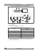
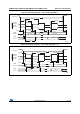
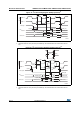
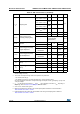
Figure 21. I
2
C bus AC waveforms and measurement circuit
1. R
S
= series protection resistor.
2. R
P
= external pull-up resistor.
3. V
DD_I2C
is the I2C bus power supply.
4.
Measurement points are done at CMOS levels: 0.3V
DD
and 0.7V
DD.
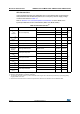
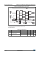
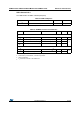
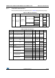
Table 49. SCL frequency (f
PCLK1
= 32 MHz, V
DD
= V
DD_I2C
= 3.3 V)
(1)(2)
1. R
P
= External pull-up resistance, f
SCL
= I
2
C speed.
2. For speeds around 200 kHz, the tolerance on the achieved speed is of 5%. For other speed ranges, the
tolerance on the achieved speed is 2%. These variations depend on the accuracy of the external
components used to design the application.
f
SCL
(kHz)
I2C_CCR value
R
P
= 4.7 k
400 0x801B
300 0x8024
200 0x8035
100 0x00A0
50 0x0140
20 0x0320
ai17855c
START
SDA
R
S
R
P
I
2
C bus
R
P
R
S
V
DD_I2C
V
DD_I2C
STM32L1xx
SDA
SCL
t
f(SDA)
t
r(SDA)
SCL
t
h(STA)
t
w(SCKH)
t
w(SCKL)
t
su(SDA)
t
r(SCK)
t
f(SCK)
t
h(SDA)
START REPEATED
START
t
su(STA)
t
su(STO)
STOP
t
su(STA:STO)