
Datasheet

Electrical characteristics STM32L15xCC STM32L15xRC STM32L15xUC STM32L15xVC
76/132 DocID022799 Rev 6
Note: For C
L1
and C
L2
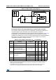
, it is recommended to use high-quality ceramic capacitors in the 5 pF to
15
pF range selected to match the requirements of the crystal or resonator (see Figure 18).
C
L1
and C
L2,
are usually the same size. The crystal manufacturer typically specifies a load
capacitance which is the series combination of C
L1
and C
L2
.
Load capacitance C
L
has the following formula: C
L
= C
L1
x C
L2
/ (C
L1
+ C
L2
) + C
stray
where
C
stray
is the pin capacitance and board or trace PCB-related capacitance. Typically, it is
between 2 pF and 7 pF.
Caution: To avoid exceeding the maximum value of C
L1
and C
L2
(15 pF) it is strongly recommended
to use a resonator with a load capacitance C
L
7 pF. Never use a resonator with a load
capacitance of 12.5 pF.
Example: if you choose a resonator with a load capacitance of C
L
= 6 pF and C
stray
= 2 pF,
then C
L1
= C
L2
= 8 pF.
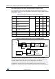
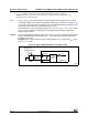
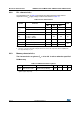
Figure 18. Typical application with a 32.768 kHz crystal
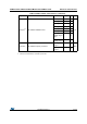
4. t
SU(LSE)
is the startup time measured from the moment it is enabled (by software) to a stabilized
32.768 kHz oscillation is reached. This value is measured for a standard crystal resonator and it can vary
significantly with the crystal manufacturer.
ai17853b
OSC32_OU T
OSC32_IN
f
LSE
CL1
R
F
STM32L1xx
32.768 kHz
resonator
CL2
Resonator with
integrated capacitors
Bias
controlled
gain