
Datasheet

DocID022799 Rev 6 75/132
STM32L15xCC STM32L15xRC STM32L15xUC STM32L15xVC Electrical characteristics
111
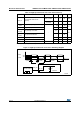
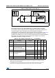
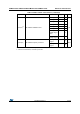
Figure 17. HSE oscillator circuit diagram
1. R
EXT
value depends on the crystal characteristics.
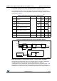
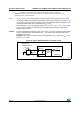
Low-speed external clock generated from a crystal/ceramic resonator
The low-speed external (LSE) clock can be supplied with a 32.768 kHz crystal/ceramic
resonator oscillator. All the information given in this paragraph are based on
characterization results obtained with typical external components specified in Table 30. In
the application, the resonator and the load capacitors have to be placed as close as
possible to the oscillator pins in order to minimize output distortion and startup stabilization
time. Refer to the crystal resonator manufacturer for more details on the resonator
characteristics (frequency, package, accuracy).
OSC_OUT
OSC_IN
f
HSE
to core
C
L1
C
L2
R
F
STM32
Resonator
Consumption
control
g
m
R
m
C
m
L
m
C
O
Resonator
ai18235b
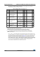
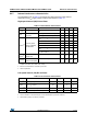
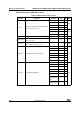
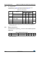
Table 30. LSE oscillator characteristics (f
LSE
= 32.768 kHz)
(1)
Symbol Parameter Conditions Min Typ Max Unit
f
LSE
Low speed external oscillator
frequency
- - 32.768 - kHz
R
F
Feedback resistor - - 1.2 - M
C
(2)
Recommended load capacitance
versus equivalent serial
resistance of the crystal (R
S
)
(3)
R
S
= 30 k -8 -pF
I
LSE
LSE driving current V
DD
= 3.3 V, V
IN
= V
SS
--1.1µA
I
DD (LSE)
LSE oscillator current
consumption
V
DD
= 1.8 V - 450 -
nAV
DD
= 3.0 V - 600 -
V
DD
= 3.6V - 750 -
g
m
Oscillator transconductance - 3 - - µA/V
t
SU(LSE)
(4)
Startup time V
DD
is stabilized - 1 - s
1. Based on characterization, not tested in production.
2. Refer to the note and caution paragraphs below the table, and to the application note AN2867 “Oscillator
design guide for ST microcontrollers”.
3. The oscillator selection can be optimized in terms of supply current using an high quality resonator with
small R
S
value for example MSIV-TIN32.768kHz. Refer to crystal manufacturer for more details.