
Datasheet


Electrical characteristics STM32L15xCC STM32L15xRC STM32L15xUC STM32L15xVC
74/132 DocID022799 Rev 6
time. Refer to the crystal resonator manufacturer for more details on the resonator
characteristics (frequency, package, accuracy).
For C
L1
and C
L2
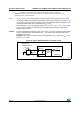
, it is recommended to use high-quality external ceramic capacitors in the
5 pF to 25 pF range (typ.), designed for high-frequency applications, and selected to match
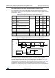
the requirements of the crystal or resonator (see Figure 17). C
L1
and C
L2
are usually the
same size. The crystal manufacturer typically specifies a load capacitance which is the
series combination of C
L1
and C
L2
. PCB and MCU pin capacitance must be included (10 pF
can be used as a rough estimate of the combined pin and board capacitance) when sizing
C
L1
and C
L2
. Refer to the application note AN2867 “Oscillator design guide for ST
microcontrollers” available from the ST website www.st.com.
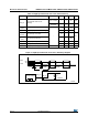
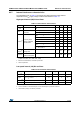
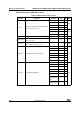
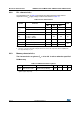
Table 29. HSE oscillator characteristics
(1)(2)
Symbol Parameter Conditions Min Typ Max Unit
f
OSC_IN
Oscillator frequency - 1 24 MHz
R
F
Feedback resistor - - 200 - k
C
Recommended load
capacitance versus
equivalent serial resistance
of the crystal (R
S
)
(3)
R
S
= 30 -20 - pF
I
HSE
HSE driving current
V
DD
= 3.3 V,
V
IN
= V
SS
with 30 pF
load
-- 3 mA
I
DD(HSE)
HSE oscillator power
consumption
C = 20 pF
f
OSC
= 16 MHz
--
2.5 (startup)
0.7 (stabilized)
mA
C = 10 pF
f
OSC
= 16 MHz
--
2.5 (startup)
0.46 (stabilized)
g
m
Oscillator
transconductance
Startup 3.5 - -
mA
/V
t
SU(HSE)
(4)
Startup time V
DD
is stabilized - 1 - ms
1. Resonator characteristics given by the crystal/ceramic resonator manufacturer.
2. Based on characterization results, not tested in production.
3. The relatively low value of the RF resistor offers a good protection against issues resulting from use in a
humid environment, due to the induced leakage and the bias condition change. However, it is
recommended to take this point into account if the MCU is used in tough humidity conditions.
4. t
SU(HSE)
is the startup time measured from the moment it is enabled (by software) to a stabilized 8 MHz
oscillation is reached. This value is measured for a standard crystal resonator and it can vary significantly
with the crystal manufacturer.