
Datasheet

Pin descriptions STM32L15xCC STM32L15xRC STM32L15xUC STM32L15xVC
44/132 DocID022799 Rev 6
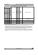
C3 97 - - - PE0 I/O FT PE0
TIM4_ETR/TIM10_CH1/
LCD_SEG36
A2 98 - - - PE1 I/O FT PE1 TIM11_CH1/LCD_SEG37
D3 99 63 A7 47 V
SS_3
SV
SS_3
C4 100 64 B7 48 V
DD_3
SV
DD_3
1. I = input, O = output, S = supply.
2. Function availability depends on the chosen device.
3. Applicable to STM32L152xC devices only. In STM32L151xC devices, this pin should be connected to V
DD
.
4. The PC14 and PC15 I/Os are only configured as OSC32_IN/OSC32_OUT when the LSE oscillator is ON (by setting the
LSEON bit in the RCC_CSR register). The LSE oscillator pins OSC32_IN/OSC32_OUT can be used as general-purpose
PH0/PH1 I/Os, respectively, when the LSE oscillator is off (after reset, the LSE oscillator is off). The LSE has priority over
the GPIO function. For more details, refer to Using the OSC32_IN/OSC32_OUT pins as GPIO PC14/PC15 port pins
section in the STM32L151xx, STM32L152xx and STM32L162xx reference manual (RM0038).
5. The PH0 and PH1 I/Os are only configured as OSC_IN/OSC_OUT when the HSE oscillator is ON (by setting the HSEON
bit in the RCC_CR register). The HSE oscillator pins OSC_IN/OSC_OUT can be used as general-purpose PH0/PH1 I/Os,
respectively, when the HSE oscillator is off ( after reset, the HSE oscillator is off ). The HSE has priority over the GPIO
function.
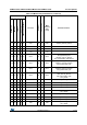
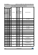
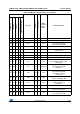
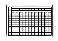
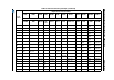
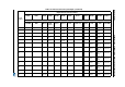
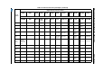
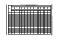
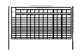
Table 9. STM32L15xxC pin definitions (continued)
Pins
Pin name
Pin type
(1)
I / O Structure
Main
function
(2)
(after
reset)
Alternate functions
UFBGA100
LQFP100
LQFP64
WLCSP63
LQFP48 or UFQFPN48