
Datasheet

DocID022799 Rev 6 129/132
STM32L15xCC STM32L15xRC STM32L15xUC STM32L15xVC Revision History
131
01-Feb-2013 3
Removed AHB1/AHB2 and corrected typo on APB1/APB2 in
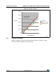
Figure 1: Ultra-low-power STM32L162xC block diagram
Updated “OP amp” line in Table 4: Functionalities depending on the
working mode (from Run/active down to standby)
Added IWDG and WWDG rows in Table 4: Functionalities depending
on the working mode (from Run/active down to standby)
Updated address range in Table 7: Internal voltage reference
measured values
The comment "HSE = 16 MHz(2) (PLL ON for fHCLK above 16
MHz)" replaced by "fHSE = fHCLK up to 16 MHz included, fHSE =
fHCLK/2 above 16 MHz (PLL ON)(2)” in table Table 19: Current
consumption in Sleep mode
replaced pin names D7,C7,C6,C8,B8,A8 respectively by
D11,D10,C12,B12,A12,A11 in column UFBGA100 of Table 10:
STM32L15xxC pin definitions
Added more alternate functions supported on pin K3 and M4 for
UFBGA100 package in Table 10: STM32L15xxC pin definitions
Added part number STM32L151CC in Table 1: Device summary
Updated Stop mode current to
1.5 µA in Ultra-low-power platform
Updated entire Section 7: Package characteristics
02-Sep-2013 4
Removed UFBGA132 and LQFP144 packages
Removed first sentence in Section : I2C interface characteristics
Added Section Table 6.: VLCD rail decoupling
Added VRAIL functions in Table 9: STM32L15xxC pin definitions
Updated PH0-OSC_IN and PH1-OSC_OUT type in Table 9:
STM32L15xxC pin definitions.
Added Table 6.1.7: Optional LCD power supply scheme.
Updated consumption data in Table 6.3.4: Supply current
characteristics
Updated Figure 6: Pin loading conditions.
Updated Figure 7: Pin input voltage.
Updated Figure 14: Typical application with a 32.768 kHz crystal.
Updated Figure 24: Recommended NRST pin protection.
Updated Figure 25: I2C bus AC waveforms and measurement circuit.
Updated Table 29: Typical connection diagram using the ADC and
definition of symbol “RAIN” in Table 56: ADC characteristics
Updated dThreshold/dt conditions in Table 64: Comparator 2
characteristics.
Updated Table 46: Thermal resistance.
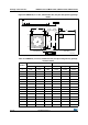
Added D2 and E2 in Table 69: UFQFPN48 – ultra thin fine pitch quad
flat pack no-lead 7 × 7 mm, 0.5 mm pitch package mechanical data
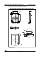
Fixed columns inversion in Table 67: LQFP64, 10 x 10 mm 64-pin
low-profile quad flat package mechanical data and Table 70:
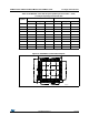
UFBGA100, 7 x 7 mm, 100-ball ultra thin, fine pitch ball grid array
package mechanical data
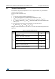
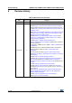
Table 74. Document revision history (continued)
Date Revision Changes