STM32L15xCC STM32L15xRC STM32L15xUC STM32L15xVC Ultra-low-power 32-bit MCU ARM-based Cortex-M3, 256KB Flash, 32KB SRAM, 8KB EEPROM, LCD, USB, ADC, DAC Datasheet - production data Features Ultra-low-power platform – 1.65 V to 3.6 V power supply – -40 °C to 85 °C/105 °C temperature range – 0.35µA Standby mode (3 wakeup pins) – 1.3 µA Standby mode + RTC – 0.65 µA Stop mode (16 wakeup lines) – 1.5 µA Stop mode + RTC – 8.
Contents STM32L15xCC STM32L15xRC STM32L15xUC STM32L15xVC Contents 1 Introduction . . . . . . . . . . . . . . . . . . . . . . . . . . . . . . . . . . . . . . . . . . . . . . . . 8 2 Description . . . . . . . . . . . . . . . . . . . . . . . . . . . . . . . . . . . . . . . . . . . . . . . . . 9 3 2/132 2.1 Device overview . . . . . . . . . . . . . . . . . . . . . . . . . . . . . . . . . . . . . . . . . . . . 10 2.2 Ultra-low-power device continuum . . . . . . . . . . . . . . . . . . . . . . . . . .
STM32L15xCC STM32L15xRC STM32L15xUC STM32L15xVC 3.16 3.17 Contents Timers and watchdogs . . . . . . . . . . . . . . . . . . . . . . . . . . . . . . . . . . . . . . . 27 3.16.1 General-purpose timers (TIM2, TIM3, TIM4, TIM5, TIM9, TIM10 and TIM11) . . . . . . . . . . . . . . . . . . . . . . . . . . . . . . . . . . . . . . . . . . . . . . . . . . 27 3.16.2 Basic timers (TIM6 and TIM7) . . . . . . . . . . . . . . . . . . . . . . . . . . . . . . . . 28 3.16.3 SysTick timer . . . . . . . . . . . . . .
Contents 7 STM32L15xCC STM32L15xRC STM32L15xUC STM32L15xVC 6.3.6 External clock source characteristics . . . . . . . . . . . . . . . . . . . . . . . . . . . 71 6.3.7 Internal clock source characteristics . . . . . . . . . . . . . . . . . . . . . . . . . . . 77 6.3.8 PLL characteristics . . . . . . . . . . . . . . . . . . . . . . . . . . . . . . . . . . . . . . . . 80 6.3.9 Memory characteristics . . . . . . . . . . . . . . . . . . . . . . . . . . . . . . . . . . . . . 80 6.3.
STM32L15xCC STM32L15xRC STM32L15xUC STM32L15xVC List of tables List of tables Table 1. Table 2. Table 3. Table 4. Table 5. Table 6. Table 7. Table 8. Table 9. Table 10. Table 11. Table 12. Table 13. Table 14. Table 15. Table 16. Table 17. Table 18. Table 19. Table 20. Table 21. Table 22. Table 23. Table 24. Table 25. Table 26. Table 27. Table 28. Table 29. Table 30. Table 31. Table 32. Table 33. Table 34. Table 35. Table 36. Table 37. Table 38. Table 39. Table 40. Table 41. Table 42. Table 43. Table 44.
List of tables Table 48. Table 49. Table 50. Table 51. Table 52. Table 53. Table 54. Table 55. Table 56. Table 57. Table 58. Table 59. Table 60. Table 61. Table 62. Table 63. Table 64. Table 65. Table 66. Table 67. Table 68. Table 69. Table 70. Table 71. Table 72. Table 73. Table 74. 6/132 STM32L15xCC STM32L15xRC STM32L15xUC STM32L15xVC I2C characteristics. . . . . . . . . . . . . . . . . . . . . . . . . . . . . . . . . . . . . . . . . . . . . . . . . . . . . . . .
STM32L15xCC STM32L15xRC STM32L15xUC STM32L15xVC List of figures List of figures Figure 1. Figure 2. Figure 3. Figure 4. Figure 5. Figure 6. Figure 7. Figure 8. Figure 9. Figure 10. Figure 11. Figure 12. Figure 13. Figure 14. Figure 15. Figure 16. Figure 17. Figure 18. Figure 19. Figure 20. Figure 21. Figure 22. Figure 23. Figure 24. Figure 25. Figure 26. Figure 27. Figure 28. Figure 29. Figure 30. Figure 31. Figure 32. Figure 33. Figure 34. Figure 35. Figure 36. Figure 37. Figure 38. Figure 39. Figure 40.
Introduction 1 STM32L15xCC STM32L15xRC STM32L15xUC STM32L15xVC Introduction This datasheet provides the ordering information and mechanical device characteristics of the medium density plus STM32L151xC and STM32L152xC ultra-low-power ARM CortexM3 based microcontrollers product line. Medium density plus STM32L15xxC devices are microcontrollers with a Flash memory density of 256 Kbytes.
STM32L15xCC STM32L15xRC STM32L15xUC STM32L15xVC 2 Description Description The medium density plus ultra-low-power STM32L15xxC incorporates the connectivity power of the universal serial bus (USB) with the high-performance ARM Cortex-M3 32-bit RISC core operating at a 32 MHz frequency, a memory protection unit (MPU), high-speed embedded memories (Flash memory up to 256 Kbytes and RAM up to 32 Kbytes) and an extensive range of enhanced I/Os and peripherals connected to two APB buses.
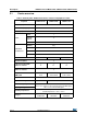
Description 2.1 STM32L15xCC STM32L15xRC STM32L15xUC STM32L15xVC Device overview Table 2. Ultralow power STM32L15xxC device features and peripheral counts Peripheral STM32L15xCC STM32L15xUC STM32L15xRC 256 Flash (Kbytes) Data EEPROM (Kbytes) 8 RAM (Kbytes) 32 Timers 32 bit 1 Generalpurpose 6 Basic 2 3/(2) SPI/(I2S) Communica tion interfaces I2C 2 USART 3 USB 1 GPIOs 37 51 12-bit synchronized ADC Number of channels 1 14 1 21 1 4x18 Max.
STM32L15xCC STM32L15xRC STM32L15xUC STM32L15xVC 2.2 Description Ultra-low-power device continuum The ultra-low-power STM32L15xxD, STM32L162xD, STM32L15xxC and STM32L162xC are fully pin-to-pin and software compatible. Besides the full compatibility within the family, the devices are part of STMicroelectronics microcontrollers ultra-low-power strategy which also includes STM8L101xx and STM8L15xx devices.
Functional overview 3 STM32L15xCC STM32L15xRC STM32L15xUC STM32L15xVC Functional overview Figure 1. Ultra-low-power STM32L15xxC block diagram TRACECK, TRACED0, TRACED1, TRACED2 J TA G & S W m ax : 32 MHz D bu s MP U S ys tem NV IC G P DMA 7 c hannels E E² obl Interfac e f @ VDD 33 P O WE R OR E VO L T . R E G .
STM32L15xCC STM32L15xRC STM32L15xUC STM32L15xVC Functional overview 1. Legend: AF: alternate function ADC: analog-to-digital converter BOR: brown out reset DMA: direct memory access DAC: digital-to-analog converter I²C: inter-integrated circuit multimaster interface 3.1 Low power modes The ultra-low-power STM32L15xxC supports dynamic voltage scaling to optimize its power consumption in run mode.
Functional overview STM32L15xCC STM32L15xRC STM32L15xUC STM32L15xVC Stop mode without RTC Stop mode achieves the lowest power consumption while retaining the RAM and register contents. All clocks are stopped, the PLL, MSI RC, HSI and LSI RC, LSE and HSE crystal oscillators are disabled. The voltage regulator is in the low power mode. The device can be woken up from Stop mode by any of the EXTI line, in 8 µs. The EXTI line source can be one of the 16 external lines.
STM32L15xCC STM32L15xRC STM32L15xUC STM32L15xVC Functional overview Table 3. Functionalities depending on the operating power supply range (continued) Functionalities depending on the operating power supply range Operating power supply range DAC and ADC operation USB Dynamic voltage scaling range I/O operation VDD=VDDA = 2.0 to 2.4 V Conversion time up to 500 Ksps Functional(2) Range 1, Range 2 or Range 3 Full speed operation VDD=VDDA = 2.4 to 3.
Functional overview STM32L15xCC STM32L15xRC STM32L15xUC STM32L15xVC Table 5.
STM32L15xCC STM32L15xRC STM32L15xUC STM32L15xVC Functional overview Table 5.
Functional overview STM32L15xCC STM32L15xRC STM32L15xUC STM32L15xVC Owing to its embedded ARM core, the STM32L15xxC is compatible with all ARM tools and software. Nested vectored interrupt controller (NVIC) The ultra-low-power STM32L15xxC embeds a nested vectored interrupt controller able to handle up to 53 maskable interrupt channels (not including the 16 interrupt lines of ARM Cortex-M3) and 16 priority levels.
STM32L15xCC STM32L15xRC STM32L15xUC STM32L15xVC Functional overview Five BOR thresholds are available through option bytes, starting from 1.8 V to 3 V. To reduce the power consumption in Stop mode, it is possible to automatically switch off the internal reference voltage (VREFINT) in Stop mode. The device remains in reset mode when VDD is below a specified threshold, VPOR/PDR or VBOR, without the need for any external reset circuit. Note: The start-up time at power-on is typically 3.
Functional overview 3.4 STM32L15xCC STM32L15xRC STM32L15xUC STM32L15xVC Clock management The clock controller distributes the clocks coming from different oscillators to the core and the peripherals. It also manages clock gating for low power modes and ensures clock robustness. It features: Clock prescaler: to get the best trade-off between speed and current consumption, the clock frequency to the CPU and peripherals can be adjusted by a programmable prescaler.
STM32L15xCC STM32L15xRC STM32L15xUC STM32L15xVC Functional overview Figure 2.
Functional overview 3.5 STM32L15xCC STM32L15xRC STM32L15xUC STM32L15xVC Low power real-time clock and backup registers The real-time clock (RTC) is an independent BCD timer/counter. Dedicated registers contain the sub-second, second, minute, hour (12/24 hour), week day, date, month, year, in BCD (binary-coded decimal) format. Correction for 28, 29 (leap year), 30, and 31 day of the month are made automatically.
STM32L15xCC STM32L15xRC STM32L15xUC STM32L15xVC 3.7 Functional overview Memories The STM32L15xxC devices have the following features: 32 Kbytes of embedded RAM accessed (read/write) at CPU clock speed with 0 wait states. With the enhanced bus matrix, operating the RAM does not lead to any performance penalty during accesses to the system bus (AHB and APB buses).
Functional overview 3.9 STM32L15xCC STM32L15xRC STM32L15xUC STM32L15xVC LCD (liquid crystal display) The LCD drives up to 8 common terminals and 44 segment terminals to drive up to 320 pixels. Internal step-up converter to guarantee functionality and contrast control irrespective of VDD.
STM32L15xCC STM32L15xRC STM32L15xUC STM32L15xVC 3.10.1 Functional overview Temperature sensor The temperature sensor (TSENSE) generates a voltage VSENSE that varies linearly with temperature. The temperature sensor is internally connected to the ADC_IN16 input channel which is used to convert the sensor output voltage into a digital value. The sensor provides good linearity but it has to be calibrated to obtain good overall accuracy of the temperature measurement.
Functional overview 3.12 STM32L15xCC STM32L15xRC STM32L15xUC STM32L15xVC Operational amplifier The STM32L15xxC embeds two operational amplifiers with external or internal follower routing capability (or even amplifier and filter capability with external components). When one operational amplifier is selected, one external ADC channel is used to enable output measurement. The operational amplifiers feature: 3.
STM32L15xCC STM32L15xRC STM32L15xUC STM32L15xVC Functional overview implementation based on a surface charge transfer acquisition principle. It consists of charging the sensor capacitance and then transferring a part of the accumulated charges into a sampling capacitor until the voltage across this capacitor has reached a specific threshold. The capacitive sensing acquisition only requires few external components to operate.
Functional overview STM32L15xCC STM32L15xRC STM32L15xUC STM32L15xVC TIM2, TIM3, TIM4, TIM5 all have independent DMA request generation. These timers are capable of handling quadrature (incremental) encoder signals and the digital outputs from 1 to 3 hall-effect sensors. TIM10, TIM11 and TIM9 TIM10 and TIM11 are based on a 16-bit auto-reload upcounter. TIM9 is based on a 16-bit auto-reload up/down counter. They include a 16-bit prescaler.
STM32L15xCC STM32L15xRC STM32L15xUC STM32L15xVC 3.17.2 Functional overview Universal synchronous/asynchronous receiver transmitter (USART) The three USART interfaces are able to communicate at speeds of up to 4 Mbit/s. They support IrDA SIR ENDEC, are ISO 7816 compliant and have LIN Master/Slave capability. The three USARTs provide hardware management of the CTS and RTS signals. All USART interfaces can be served by the DMA controller. 3.17.
Functional overview 3.19 STM32L15xCC STM32L15xRC STM32L15xUC STM32L15xVC Development support Serial wire JTAG debug port (SWJ-DP) The ARM SWJ-DP interface is embedded, and is a combined JTAG and serial wire debug port that enables either a serial wire debug or a JTAG probe to be connected to the target. The JTAG JTMS and JTCK pins are shared with SWDAT and SWCLK, respectively, and a specific sequence on the JTMS pin is used to switch between JTAG-DP and SW-DP.
STM32L15xCC STM32L15xRC STM32L15xUC STM32L15xVC 4 Pin descriptions Pin descriptions Figure 3.
Pin descriptions STM32L15xCC STM32L15xRC STM32L15xUC STM32L15xVC 100 99 98 97 96 95 94 93 92 91 90 89 88 87 86 85 84 83 82 81 80 79 78 77 76 VDD_3 VSS_3 PE1 PE0 PB9 PB8 BOOT0 PB7 PB6 PB5 PB4 PB3 PD7 PD6 PD5 PD4 PD3 PD2 PD1 PD0 PC12 PC11 PC10 PA15 PA14 Figure 4.
STM32L15xCC STM32L15xRC STM32L15xUC STM32L15xVC Pin descriptions VDD_3 VSS_3 PB9 PB8 BOOT0 PB7 PB6 PB5 PB4 PB3 PD2 PC12 PC11 PC10 PA15 PA14 Figure 5.
Pin descriptions STM32L15xCC STM32L15xRC STM32L15xUC STM32L15xVC Figure 6.
STM32L15xCC STM32L15xRC STM32L15xUC STM32L15xVC Pin descriptions PA15 PA14 38 37 VDD_2 PC13-WKUP2 2 35 VSS_2 PC14-OSC32_IN 3 34 PA13 PC15-OSC32_OUT 4 33 PA12 PH0-OSC_IN 5 32 PA11 PH1-OSC_OUT 6 31 PA10 NRST 7 30 PA9 VSSA 8 29 PA8 VDDA 9 28 PB15 PA0-WKUP1 10 27 PB14 PA1 11 26 PB13 PA2 12 13 15 16 17 18 19 20 21 22 23 25 24 PB12 14 PB11 UFQFPN48 VDD_1 36 VSS_1 PB3 PB4 PB5 39 PB10 40 PB2 41 PB1 42 PB0 43 PB6 PB7 BOOT0 44 PA7 PB8 45
Pin descriptions STM32L15xCC STM32L15xRC STM32L15xUC STM32L15xVC VDD_3 VSS_3 PB9 PB8 BOOT0 PB7 PB6 PB5 PB4 PB3 PA15 PA14 Figure 8.
STM32L15xCC STM32L15xRC STM32L15xUC STM32L15xVC Pin descriptions Table 8. Legend/abbreviations used in the pinout table Name Pin name Pin type I/O structure Notes Abbreviation Definition Unless otherwise specified in brackets below the pin name, the pin function during and after reset is the same as the actual pin name S Supply pin I Input only pin I/O Input / output pin FT 5 V tolerant I/O TC Standard 3.
Pin descriptions STM32L15xCC STM32L15xRC STM32L15xUC STM32L15xVC Table 9.
STM32L15xCC STM32L15xRC STM32L15xUC STM32L15xVC Pin descriptions Table 9.
Pin descriptions STM32L15xCC STM32L15xRC STM32L15xUC STM32L15xVC Table 9.
STM32L15xCC STM32L15xRC STM32L15xUC STM32L15xVC Pin descriptions Table 9.
Pin descriptions STM32L15xCC STM32L15xRC STM32L15xUC STM32L15xVC Table 9.
STM32L15xCC STM32L15xRC STM32L15xUC STM32L15xVC Pin descriptions Table 9.
Pin descriptions STM32L15xCC STM32L15xRC STM32L15xUC STM32L15xVC Table 9. STM32L15xxC pin definitions (continued) UFBGA100 LQFP100 LQFP64 WLCSP63 LQFP48 or UFQFPN48 Pin type(1) I / O Structure Pins Main function(2) (after reset) C3 97 - - - PE0 I/O FT PE0 TIM4_ETR/TIM10_CH1/ LCD_SEG36 A2 98 - - - PE1 I/O FT PE1 TIM11_CH1/LCD_SEG37 D3 99 63 A7 47 VSS_3 S VSS_3 C4 100 64 B7 48 VDD_3 S VDD_3 Pin name Alternate functions 1. I = input, O = output, S = supply. 2.
Digital alternate function number AFIO0 AFIO1 AFIO2 AFIO3 AFIO4 Port name AFIO5 AFIO6 AFIO7 . AFIO10 . AFIO11 . .
Digital alternate function number AFIO0 AFIO1 AFIO2 AFIO3 AFIO4 Port name AFIO5 AFIO6 AFIO7 . AFIO10 . AFIO11 . .
Digital alternate function number AFIO0 AFIO1 AFIO2 AFIO3 AFIO4 Port name AFIO5 AFIO6 AFIO7 . AFIO10 . AFIO11 . .
Digital alternate function number AFIO0 AFIO1 AFIO2 AFIO3 AFIO4 Port name AFIO5 AFIO6 AFIO7 . AFIO10 . AFIO11 . .
Digital alternate function number AFIO0 AFIO1 AFIO2 AFIO3 AFIO4 Port name AFIO5 AFIO6 AFIO7 . AFIO10 . AFIO11 . .
Digital alternate function number AFIO0 AFIO1 AFIO2 AFIO3 AFIO4 Port name AFIO5 AFIO6 AFIO7 . AFIO10 . AFIO11 . .
STM32L15xCC STM32L15xRC STM32L15xUC STM32L15xVC 5 Memory mapping Memory mapping Figure 9.
Electrical characteristics STM32L15xCC STM32L15xRC STM32L15xUC STM32L15xVC 6 Electrical characteristics 6.1 Parameter conditions Unless otherwise specified, all voltages are referenced to VSS. 6.1.
STM32L15xCC STM32L15xRC STM32L15xUC STM32L15xVC Power supply scheme Figure 12. Power supply scheme Standby-power circuitry (OSC32K,RTC, Wake-up logic RTC backup registers) OUT GP I/Os IN VDD VDD1/2/.../N Level shifter 6.1.6 Electrical characteristics IO Logic Kernel logic (CPU, Digital & Memories) Regulator N × 100 nF + 1 × 10 μF VSS1/2/.../N VDDA VDDA VREF 100 nF + 1 μF 100 nF + 1 μF VREF+ VREF- ADC/ DAC Analog: RCS,PLL,COMP, ….
Electrical characteristics 6.1.7 STM32L15xCC STM32L15xRC STM32L15xUC STM32L15xVC Optional LCD power supply scheme Figure 13. Optional LCD power supply scheme VSEL VDD VDD1/2/.../N Step-up Converter N x 100 nF + 1 x 10 μF Option 1 VLCD 100 nF VLCD Option 2 CEXT LCD PB0 or PE12 PB2 PB12 or PE11 Crail3 Crail2 VLCDrail3 VLCDrail2 VLCDrail1 Crail1 VSS1/2/.../N MS32485V1 1. Option 1: LCD power supply is provided by a dedicated VLCD supply source, VSEL switch is open. 2.
STM32L15xCC STM32L15xRC STM32L15xUC STM32L15xVC 6.2 Electrical characteristics Absolute maximum ratings Stresses above the absolute maximum ratings listed in Table 11: Voltage characteristics, Table 12: Current characteristics, and Table 13: Thermal characteristics may cause permanent damage to the device. These are stress ratings only and functional operation of the device at these conditions is not implied. Exposure to maximum rating conditions for extended periods may affect device reliability.
Electrical characteristics STM32L15xCC STM32L15xRC STM32L15xUC STM32L15xVC 4. Positive current injection is not possible on these I/Os. A negative injection is induced by VIN VDD while a negative injection is induced by VIN < VSS. IINJ(PIN) must never be exceeded. Refer to Table 11: Voltage characteristics for the maximum allowed input voltage values. 6.
STM32L15xCC STM32L15xRC STM32L15xUC STM32L15xVC Electrical characteristics Table 14. General operating conditions (continued) Symbol TA TJ Parameter Conditions Temperature range Junction temperature range Min Max Maximum power dissipation –40 85 Low power dissipation(5) –40 105 -40 °C TA 105 °C –40 105 Unit °C °C 1. When the ADC is used, refer to Table 56: ADC characteristics. 2. It is recommended to power VDD and VDDA from the same source.
Electrical characteristics STM32L15xCC STM32L15xRC STM32L15xUC STM32L15xVC Table 15. Embedded reset and power control block characteristics (continued) Symbol Parameter Conditions VBOR3 Brown-out reset threshold 3 VBOR4 Brown-out reset threshold 4 VPVD0 Programmable voltage detector threshold 0 VPVD1 PVD threshold 1 VPVD2 PVD threshold 2 VPVD3 PVD threshold 3 VPVD4 PVD threshold 4 VPVD5 PVD threshold 5 VPVD6 PVD threshold 6 Vhyst Hysteresis voltage Min Typ Max Falling edge 2.
STM32L15xCC STM32L15xRC STM32L15xUC STM32L15xVC 6.3.3 Electrical characteristics Embedded internal reference voltage The parameters given in Table 17 are based on characterization results, unless otherwise specified. Table 16. Embedded internal reference voltage calibration values Calibration value name Description Memory address Raw data acquired at temperature of 30 °C ±5 °C VDDA= 3 V ±10 mV VREFINT_CAL 0x1FF8 00F8 - 0x1FF8 00F9 Table 17.
Electrical characteristics STM32L15xCC STM32L15xRC STM32L15xUC STM32L15xVC 3. Guaranteed by design, not tested in production. 4. Shortest sampling time can be determined in the application by multiple iterations. 5. To guarantee less than 1% VREF_OUT deviation.
STM32L15xCC STM32L15xRC STM32L15xUC STM32L15xVC 6.3.4 Electrical characteristics Supply current characteristics The current consumption is a function of several parameters and factors such as the operating voltage, ambient temperature, I/O pin loading, device software configuration, operating frequencies, I/O pin switching rate, program location in memory and executed binary code. The current consumption is measured as described in Figure 14: Current consumption measurement scheme.
Electrical characteristics STM32L15xCC STM32L15xRC STM32L15xUC STM32L15xVC 2. Oscillator bypassed (HSEBYP = 1 in RCC_CR register). Table 19. Current consumption in Run mode, code with data processing running from RAM Symbol Parameter fHSE = fHCLK up to 16 MHz, included fHSE = fHCLK/2 above 16 MHz (PLL ON)(2) IDD (Run from RAM) Typ Max(1) 1 MHz Range 3, VCORE=1.2 V VOS[1:0] 2 MHz = 11 4 MHz 160 240 310 410 4 MHz Range 2, VCORE=1.5 V VOS[1:0] 8 MHz = 10 16 MHz 0.79 1.4 1.55 2.1 3.
STM32L15xCC STM32L15xRC STM32L15xUC STM32L15xVC Electrical characteristics Table 20. Current consumption in Sleep mode Symbol Parameter Conditions Range 3, VCORE=1.2 V VOS[1:0] = 11 fHSE = fHCLK up to 16 MHz included, Range 2, fHSE = fHCLK/2 VCORE=1.5 V above 16 MHz (PLL VOS[1:0] = 10 ON)(2) Supply current in Sleep mode, Flash OFF HSI clock source (16 MHz) Typ Max(1) 1 MHz 70 130 2 MHz 130 195 4 MHz 245 310 4 MHz 250 310 8 MHz 365 440 16 MHz 735 830 Range 1, VCORE=1.
Electrical characteristics STM32L15xCC STM32L15xRC STM32L15xUC STM32L15xVC 1. Based on characterization, not tested in production, unless otherwise specified. 2. Oscillator bypassed (HSEBYP = 1 in RCC_CR register) - Symbol Table 21. Current consumption in Low power run mode Parameter Typ Max(1) TA = -40 °C to 25 °C 8.
STM32L15xCC STM32L15xRC STM32L15xUC STM32L15xVC Electrical characteristics Table 22. Current consumption in Low power sleep mode Symbol Parameter MSI clock, 65 kHz fHCLK = 32 kHz Flash OFF MSI clock, 65 kHz fHCLK = 32 kHz Flash ON All peripherals OFF, VDD from 1.65 V to 3.6 V IDD (LP Sleep) Typ Max(1) TA = -40 °C to 25 °C 4.
Electrical characteristics STM32L15xCC STM32L15xRC STM32L15xUC STM32L15xVC Table 23. Typical and maximum current consumptions in Stop mode Symbol Parameter Conditions LCD OFF RTC clocked by LSI or LSE external clock (32.768kHz), regulator in LP mode,HSI and HSE OFF (no independent watchdog) Typ TA = -40°C to 25°C VDD = 1.8 V 1.5 TA = -40°C to 25°C 1.7 4 TA = 55°C 2.4 6 TA= 85°C 5.4 10 TA = 105°C 11.0 23 3.8 6 4.
STM32L15xCC STM32L15xRC STM32L15xUC STM32L15xVC Electrical characteristics Table 23. Typical and maximum current consumptions in Stop mode (continued) Symbol Parameter Regulator in LP mode, HSI and HSE OFF, independent watchdog and LSI enabled IDD (Stop) Supply current in Stop mode (RTC disabled) IDD Supply current during (WU from wakeup from Stop Stop) mode Typ Max(1) TA = -40°C to 25°C 1.6 2.2 TA = -40°C to 25°C 0.65 1 TA = 55°C 1.3 3 TA= 85°C 4.4 9 TA = 105°C 10.0 22(5) 2 - 1.
Electrical characteristics STM32L15xCC STM32L15xRC STM32L15xUC STM32L15xVC 2. Tested in production. 3. Based on characterization done with a 32.768 kHz crystal (MC306-G-06Q-32.768, manufacturer JFVNY) with two 6.8pF loading capacitors. On-chip peripheral current consumption The current consumption of the on-chip peripherals is given in the following table.
STM32L15xCC STM32L15xRC STM32L15xUC STM32L15xVC Electrical characteristics Table 25. Peripheral current consumption(1) (continued) Typical consumption, VDD = 3.0 V, TA = 25 °C Range 1, VCORE= 1.8 V VOS[1:0] = 01 Range 2, VCORE= 1.5 V VOS[1:0] = 10 Range 3, VCORE= 1.
Electrical characteristics STM32L15xCC STM32L15xRC STM32L15xUC STM32L15xVC 3. In low power sleep and run mode, the Flash memory must always be in power-down mode. 4. Data based on a differential IDD measurement between ADC in reset configuration and continuous ADC conversion (HSI consumption not included). 5. Data based on a differential IDD measurement between DAC in reset configuration and continuous DAC conversion of VDD/2. DAC is in buffered mode, output is left floating. 6.
STM32L15xCC STM32L15xRC STM32L15xUC STM32L15xVC 6.3.6 Electrical characteristics External clock source characteristics High-speed external user clock generated from an external source In bypass mode the HSE oscillator is switched off and the input pin is a standard GPIO.The external clock signal has to respect the I/O characteristics in Section 6.3.12. However, the recommended clock input waveform is shown in Figure 15.
Electrical characteristics STM32L15xCC STM32L15xRC STM32L15xUC STM32L15xVC Table 27. High-speed external user clock characteristics(1) Symbol fHSE_ext Parameter User external clock source frequency Conditions Min Typ Max Unit CSS is on or PLL is used 1 8 32 MHz CSS is off, PLL not used 0 8 32 MHz VHSEH OSC_IN input pin high level voltage 0.7VDD - VDD VHSEL OSC_IN input pin low level voltage VSS - 0.
STM32L15xCC STM32L15xRC STM32L15xUC STM32L15xVC Electrical characteristics Low-speed external user clock generated from an external source The characteristics given in the following table result from tests performed using a lowspeed external clock source, and under ambient temperature and supply voltage conditions summarized in Table 14. Table 28.
Electrical characteristics STM32L15xCC STM32L15xRC STM32L15xUC STM32L15xVC time. Refer to the crystal resonator manufacturer for more details on the resonator characteristics (frequency, package, accuracy). Table 29.
STM32L15xCC STM32L15xRC STM32L15xUC STM32L15xVC Electrical characteristics Figure 17. HSE oscillator circuit diagram fHSE to core Rm Lm RF CO CL1 OSC_IN Cm gm Resonator Consumption control Resonator STM32 OSC_OUT CL2 ai18235b 1. REXT value depends on the crystal characteristics. Low-speed external clock generated from a crystal/ceramic resonator The low-speed external (LSE) clock can be supplied with a 32.768 kHz crystal/ceramic resonator oscillator.
Electrical characteristics 4. STM32L15xCC STM32L15xRC STM32L15xUC STM32L15xVC tSU(LSE) is the startup time measured from the moment it is enabled (by software) to a stabilized 32.768 kHz oscillation is reached. This value is measured for a standard crystal resonator and it can vary significantly with the crystal manufacturer.
STM32L15xCC STM32L15xRC STM32L15xUC STM32L15xVC 6.3.7 Electrical characteristics Internal clock source characteristics The parameters given in Table 31 are derived from tests performed under ambient temperature and VDD supply voltage conditions summarized in Table 14. High-speed internal (HSI) RC oscillator Table 31. HSI oscillator characteristics Symbol fHSI TRIM (1)(2) Parameter Conditions Min Typ Max Unit Frequency VDD = 3.
Electrical characteristics STM32L15xCC STM32L15xRC STM32L15xUC STM32L15xVC Multi-speed internal (MSI) RC oscillator Table 33. MSI oscillator characteristics Symbol Condition Typ MSI range 0 65.5 - MSI range 1 131 - MSI range 2 262 - MSI range 3 524 - MSI range 4 1.05 - MSI range 5 2.1 - MSI range 6 4.2 - Frequency error after factory calibration - 0.
STM32L15xCC STM32L15xRC STM32L15xUC STM32L15xVC Electrical characteristics Table 33. MSI oscillator characteristics (continued) Symbol tSTAB(MSI)(2) fOVER(MSI) Parameter MSI oscillator stabilization time MSI oscillator frequency overshoot Condition Typ Max Unit MSI range 0 - 40 MSI range 1 - 20 MSI range 2 - 10 MSI range 3 - 4 MSI range 4 - 2.
Electrical characteristics 6.3.8 STM32L15xCC STM32L15xRC STM32L15xUC STM32L15xVC PLL characteristics The parameters given in Table 34 are derived from tests performed under ambient temperature and VDD supply voltage conditions summarized in Table 14. Table 34.
STM32L15xCC STM32L15xRC STM32L15xUC STM32L15xVC Electrical characteristics Flash memory and data EEPROM Table 36. Flash memory and data EEPROM characteristics Symbol Conditions Min Typ Max(1) Unit - 1.65 - 3.6 V Erasing - 3.28 3.94 Programming - 3.28 3.94 Average current during the whole programming / erase operation - 600 900 µA Maximum current (peak) TA25 °C, VDD = 3.6 V during the whole programming / erase operation - 1.5 2.
Electrical characteristics 6.3.10 STM32L15xCC STM32L15xRC STM32L15xUC STM32L15xVC EMC characteristics Susceptibility tests are performed on a sample basis during device characterization. Functional EMS (electromagnetic susceptibility) While a simple application is executed on the device (toggling 2 LEDs through I/O ports). the device is stressed by two electromagnetic events until a failure occurs.
STM32L15xCC STM32L15xRC STM32L15xUC STM32L15xVC Electrical characteristics To complete these trials, ESD stress can be applied directly on the device, over the range of specification values. When unexpected behavior is detected, the software can be hardened to prevent unrecoverable errors occurring (see application note AN1015). Electromagnetic Interference (EMI) The electromagnetic field emitted by the device are monitored while a simple application is executed (toggling 2 LEDs through the I/O ports).
Electrical characteristics STM32L15xCC STM32L15xRC STM32L15xUC STM32L15xVC Static latch-up Two complementary static tests are required on six parts to assess the latch-up performance: A supply overvoltage is applied to each power supply pin A current injection is applied to each input, output and configurable I/O pin These tests are compliant with EIA/JESD 78A IC latch-up standard. Table 41. Electrical sensitivities Symbol LU 6.3.
STM32L15xCC STM32L15xRC STM32L15xUC STM32L15xVC 6.3.13 Electrical characteristics I/O port characteristics General input/output characteristics Unless otherwise specified, the parameters given in Table 43 are derived from tests performed under the conditions summarized in Table 14. All I/Os are CMOS and TTL compliant. Table 43.
Electrical characteristics STM32L15xCC STM32L15xRC STM32L15xUC STM32L15xVC In the user application, the number of I/O pins which can drive current must be limited to respect the absolute maximum rating specified in Section 6.2: The sum of the currents sourced by all the I/Os on VDD, plus the maximum Run consumption of the MCU sourced on VDD, cannot exceed the absolute maximum rating IVDD(x) (see Table 12).
STM32L15xCC STM32L15xRC STM32L15xUC STM32L15xVC Electrical characteristics Input/output AC characteristics The definition and values of input/output AC characteristics are given in Figure 19 and Table 45, respectively. Unless otherwise specified, the parameters given in Table 45 are derived from tests performed under ambient temperature and VDD supply voltage conditions summarized in Table 14. Table 45.
Electrical characteristics STM32L15xCC STM32L15xRC STM32L15xUC STM32L15xVC Figure 19. I/O AC characteristics definition 90% 10% 50% 50% 90% 10% EXTERNAL OUTPUT ON 50pF tr(IO)out tf(IO)out T Maximum frequency is achieved if (tr + tf) ≤ 2/3)T and if the duty cycle is (45-55%) when loaded by 50pF ai14131c 6.3.14 NRST pin characteristics The NRST pin input driver uses CMOS technology.
STM32L15xCC STM32L15xRC STM32L15xUC STM32L15xVC Electrical characteristics Figure 20. Recommended NRST pin protection External reset circuit(1) NRST(2) VDD RPU Internal reset Filter 0.1 μF STM32L1xx ai17854b 1. The reset network protects the device against parasitic resets. 2. The user must ensure that the level on the NRST pin can go below the VIL(NRST) max level specified in Table 46. Otherwise the reset will not be taken into account by the device. 6.3.
Electrical characteristics 6.3.16 STM32L15xCC STM32L15xRC STM32L15xUC STM32L15xVC Communications interfaces I2C interface characteristics The STM32L15xxC product line I2C interface meets the requirements of the standard I2C communication protocol with the following restrictions: SDA and SCL are not “true” opendrain I/O pins. When configured as open-drain, the PMOS connected between the I/O pin and VDD is disabled, but is still present. The I2C characteristics are described in Table 48.
STM32L15xCC STM32L15xRC STM32L15xUC STM32L15xVC Electrical characteristics Figure 21. I2C bus AC waveforms and measurement circuit VDD_I2C VDD_I2C RP RP STM32L1xx RS SDA I2C bus RS SCL S TART REPEATED S TART S TART tsu(STA) SDA tf(SDA) tr(SDA) tsu(SDA) th(STA) tw(SCKL) th(SDA) tsu(STA:STO) S TOP SCL tr(SCK) tw(SCKH) tf(SCK) tsu(STO) ai17855c 1. RS = series protection resistor. 2. RP = external pull-up resistor. 3. VDD_I2C is the I2C bus power supply. 4.
Electrical characteristics STM32L15xCC STM32L15xRC STM32L15xUC STM32L15xVC SPI characteristics Unless otherwise specified, the parameters given in the following table are derived from tests performed under ambient temperature, fPCLKx frequency and VDD supply voltage conditions summarized in Table 14. Refer to Section 6.3.12: I/O current injection characteristics for more details on the input/output alternate function characteristics (NSS, SCK, MOSI, MISO). Table 50.
STM32L15xCC STM32L15xRC STM32L15xUC STM32L15xVC Electrical characteristics Figure 22. SPI timing diagram - slave mode and CPHA = 0 NSS input tc(SCK) th(NSS) SCK Input tSU(NSS) CPHA= 0 CPOL=0 tw(SCKH) tw(SCKL) CPHA= 0 CPOL=1 tv(SO) ta(SO) MISO OUT P UT tr(SCK) tf(SCK) th(SO) MS B O UT BI T6 OUT tdis(SO) LSB OUT tsu(SI) MOSI I NPUT B I T1 IN M SB IN LSB IN th(SI) ai14134c Figure 23.
Electrical characteristics STM32L15xCC STM32L15xRC STM32L15xUC STM32L15xVC Figure 24. SPI timing diagram - master mode(1) High NSS input SCK Input CPHA= 0 CPOL=0 SCK Input tc(SCK) CPHA=1 CPOL=0 CPHA= 0 CPOL=1 CPHA=1 CPOL=1 tsu(MI) MISO INP UT tw(SCKH) tw(SCKL) tr(SCK) tf(SCK) MS BIN BI T6 IN LSB IN th(MI) MOSI OUTPUT M SB OUT B I T1 OUT tv(MO) LSB OUT th(MO) ai14136 1. Measurement points are done at CMOS levels: 0.3VDD and 0.7VDD. I2S characteristics Table 51.
STM32L15xCC STM32L15xRC STM32L15xUC STM32L15xVC Electrical characteristics Table 51.
Electrical characteristics STM32L15xCC STM32L15xRC STM32L15xUC STM32L15xVC Figure 25. I2S slave timing diagram (Philips protocol)(1) CK Input tc(CK) CPOL = 0 CPOL = 1 tw(CKH) th(WS) tw(CKL) WS input tv(SD_ST) tsu(WS) SDtransmit LSB transmit(2) MSB transmit Bitn transmit tsu(SD_SR) LSB receive(2) SDreceive th(SD_ST) LSB transmit th(SD_SR) MSB receive Bitn receive LSB receive ai14881b 1. Measurement points are done at CMOS levels: 0.3 × VDD and 0.7 × VDD. 2.
STM32L15xCC STM32L15xRC STM32L15xUC STM32L15xVC Electrical characteristics USB characteristics The USB interface is USB-IF certified (full speed). Table 52. USB startup time Symbol tSTARTUP (1) Parameter USB transceiver startup time Max Unit 1 µs 1. Guaranteed by design, not tested in production. Table 53. USB DC electrical characteristics Symbol Parameter Conditions Min.(1) Max.(1) Unit - 3.0 3.6 V 0.
Electrical characteristics STM32L15xCC STM32L15xRC STM32L15xUC STM32L15xVC Figure 27. USB timings: definition of data signal rise and fall time Crossover points Differen tial Data L ines VCRS VS S tr tf ai14137 Table 54. USB: full speed electrical characteristics Driver characteristics(1) Symbol Parameter Conditions Min Max Unit tr Rise time(2) CL = 50 pF 4 20 ns tf Time(2) CL = 50 pF 4 20 ns tr/tf 90 110 % 1.3 2.
STM32L15xCC STM32L15xRC STM32L15xUC STM32L15xVC 6.3.17 Electrical characteristics 12-bit ADC characteristics Unless otherwise specified, the parameters given in Table 56 are guaranteed by design. Table 55. ADC clock frequency Symbol fADC Parameter ADC clock frequency Conditions Voltage range 1 & 2 Min Max VREF+ = VDDA 16 VREF+ VDDA 2.4 V VDDA 3.6 V VREF+ > 2.4 V 8 VREF+ VDDA VREF+ 2.4 V 1.8 V VDDA 2.4 V 0.
Electrical characteristics STM32L15xCC STM32L15xRC STM32L15xUC STM32L15xVC Table 56. ADC characteristics (continued) Symbol tS(5) Parameter Sampling time tCONV Total conversion time (including sampling time) CADC Internal sample and hold capacitor fTRIG External trigger frequency Regular sequencer fTRIG External trigger frequency Injected sequencer RAIN(6) Signal source impedance Conditions Min Typ Max Direct channels 2.4 V VDDA 3.6 V 0.25 - - Multiplexed channels 2.
STM32L15xCC STM32L15xRC STM32L15xUC STM32L15xVC Electrical characteristics Table 57.
Electrical characteristics STM32L15xCC STM32L15xRC STM32L15xUC STM32L15xVC Figure 28. ADC accuracy characteristics V V [1LSBIDEAL = REF+ (or DDA depending on package)] 4096 4096 EG 4095 4094 (1) Example of an actual transfer curve (2) The ideal transfer curve (3) End point correlation line 4093 (2) ET 7 (1) 6 5 4 ET=Total Unadjusted Error: maximum deviation between the actual and the ideal transfer curves. EO=Offset Error: deviation between the first actual transition and the first ideal one.
STM32L15xCC STM32L15xRC STM32L15xUC STM32L15xVC Electrical characteristics Figure 30. Maximum dynamic current consumption on VREF+ supply pin during ADC conversion Sampling (n cycles) Conversion (12 cycles) ADC clock Iref+ 700µA 300µA Table 58. RAIN max for fADC = 16 MHz(1) RAIN max (k) Ts (cycles) Ts (µs) Multiplexed channels Direct channels 2.4 V < VDDA < 3.6 V 1.8 V < VDDA < 2.4 V 2.4 V < VDDA < 3.6 V 1.8 V < VDDA < 2.4 V 4 0.25 Not allowed Not allowed 0.7 Not allowed 9 0.5625 0.
Electrical characteristics STM32L15xCC STM32L15xRC STM32L15xUC STM32L15xVC Figure 31. Power supply and reference decoupling (VREF+ not connected to VDDA) STM32L15xxx VREF+ (see note 1) 1 μF // 100 nF VDDA 1 μF // 100 nF VSSA /VREF– (see note 1) ai17857b 1. VREF+ and VREF– inputs are available only on 100-pin packages. Figure 32. Power supply and reference decoupling (VREF+ connected to VDDA) STM32L15xxx VREF+/VDDA (See note 1) 1 μF // 100 nF VREF–/VSSA (See note 1) ai17858a 1.
STM32L15xCC STM32L15xRC STM32L15xUC STM32L15xVC 6.3.18 Electrical characteristics DAC electrical specifications Data guaranteed by design, not tested in production, unless otherwise specified. Table 59. DAC characteristics Symbol Parameter Conditions VDDA Analog supply voltage VREF+ Reference supply voltage VREF- Lower reference voltage IDDVREF+(1) Current consumption on No load, middle code (0x800) VREF+ supply No load, worst code (0x000) VREF+ = 3.
Electrical characteristics STM32L15xCC STM32L15xRC STM32L15xUC STM32L15xVC Table 59. DAC characteristics (continued) Symbol Parameter Conditions VDDA 3.3V VREF+ 3.0V TA = 0 to 50 C DAC output buffer OFF Offset error temperature dOffset/dT(1) coefficient (code 0x800) V 3.3V Min Typ Max -20 -10 0 Unit µV/°C DDA VREF+ 3.0V TA = 0 to 50 C DAC output buffer ON 0 20 50 CL 50 pF, RL 5 k DAC output buffer ON - +0.1 / -0.2% +0.2 / -0.
STM32L15xCC STM32L15xRC STM32L15xUC STM32L15xVC Electrical characteristics 4. Difference between measured value at Code i and the value at Code i on a line drawn between Code 0 and last Code 4095. 5. Difference between the value measured at Code (0x800) and the ideal value = VREF+/2. 6. Difference between the value measured at Code (0x001) and the ideal value. 7.
Electrical characteristics STM32L15xCC STM32L15xRC STM32L15xUC STM32L15xVC Table 60. Operational amplifier characteristics (continued) Symbol Condition(1) Parameter Normal mode GBW Bandwidth Low power mode Normal mode Low power mode SR Slew rate VDD>2.4 V VDD<2.4 V Min(2) Typ Max(2) 400 1000 3000 150 300 800 200 500 2200 70 150 800 Normal mode VDD>2.4 V (between 0.1 V and VDD-0.1 V) - 700 - Low power mode VDD>2.
STM32L15xCC STM32L15xRC STM32L15xUC STM32L15xVC 6.3.20 Electrical characteristics Temperature sensor characteristics Table 61. Temperature sensor calibration values Calibration value name Description Memory address TS_CAL1 TS ADC raw data acquired at temperature of 30 °C 5 °C VDDA= 3 V 10 mV 0x1FF8 00FA - 0x1FF8 00FB TS_CAL2 TS ADC raw data acquired at temperature of 110 °C 5 °C VDDA= 3 V 10 mV 0x1FF8 00FE - 0x1FF8 00FF Table 62.
Electrical characteristics STM32L15xCC STM32L15xRC STM32L15xUC STM32L15xVC Table 63. Comparator 1 characteristics (continued) Symbol dVoffset/dt ICOMP1 Min(1) Typ Max(1) Unit VDDA 3.6 V Comparator offset VIN+ 0 V variation in worst voltage VIN- VREFINT stress conditions TA = 25 C 0 1.5 10 mV/1000 h Current consumption(3) - 160 260 nA Parameter Conditions - 1. Based on characterization, not tested in production. 2.
STM32L15xCC STM32L15xRC STM32L15xUC STM32L15xVC 6.3.22 Electrical characteristics LCD controller The STM32L15xxC embeds a built-in step-up converter to provide a constant LCD reference voltage independently from the VDD voltage. An external capacitor Cext must be connected to the VLCD pin to decouple this converter. Table 65. LCD controller characteristics Symbol Parameter Min Typ Max Unit VLCD LCD external voltage - - 3.6 VLCD0 LCD internal reference voltage 0 - 2.
Package characteristics STM32L15xCC STM32L15xRC STM32L15xUC STM32L15xVC 7 Package characteristics 7.1 Package mechanical data In order to meet environmental requirements, ST offers these devices in different grades of ECOPACK® packages, depending on their level of environmental compliance. ECOPACK® specifications, grade definitions and product status are available at: www.st.com. ECOPACK® is an ST trademark. Figure 34.
STM32L15xCC STM32L15xRC STM32L15xUC STM32L15xVC Package characteristics Table 66. LQPF100, 14 x 14 mm, 100-pin low-profile quad flat package mechanical data inches(1) millimeters Symbol Min Typ Max Min Typ Max A - - 1.600 - - 0.0630 A1 0.050 - 0.150 0.0020 - 0.0059 A2 1.350 1.400 1.450 0.0531 0.0551 0.0571 b 0.170 0.220 0.270 0.0067 0.0087 0.0106 c 0.090 - 0.200 0.0035 - 0.0079 D 15.800 16.000 16.200 0.6220 0.6299 0.6378 D1 13.800 14.000 14.200 0.
Package characteristics STM32L15xCC STM32L15xRC STM32L15xUC STM32L15xVC Marking of engineering samples The following figure shows the engineering sample marking for the LQFP100 package. Only the information field containing the engineering sample marking is shown. Figure 36. LQFP100 package top view Engineering sample marking1 ES MS33007V1 1. Samples marked “ES” are to be considered as “Engineering Samples”: i.e.
STM32L15xCC STM32L15xRC STM32L15xUC STM32L15xVC Package characteristics Figure 37. LQFP64, 10 x 10 mm, 64-pin low-profile quad flat package outline c A1 A A2 SEATING PLANE C 0.25 mm GAUGE PLANE A1 ccc C K L D L1 D1 D3 33 48 32 49 64 PIN 1 IDENTIFICATION E E1 E3 b 17 16 1 e 5W_ME_V2 1. Drawing is not to scale.
Package characteristics STM32L15xCC STM32L15xRC STM32L15xUC STM32L15xVC Table 67. LQFP64, 10 x 10 mm 64-pin low-profile quad flat package mechanical data inches(1) millimeters Symbol Min Typ Max Min Typ Max A - - 1.600 - - 0.0630 A1 0.050 - 0.150 0.0020 - 0.0059 A2 1.350 1.400 1.450 0.0531 0.0551 0.0571 b 0.170 0.220 0.270 0.0067 0.0087 0.0106 c 0.090 - 0.200 0.0035 - 0.0079 D 11.800 12.000 12.200 0.4646 0.4724 0.4803 D1 9.800 10.000 10.200 0.3858 0.
STM32L15xCC STM32L15xRC STM32L15xUC STM32L15xVC Package characteristics Marking of engineering samples The following figure shows the engineering sample marking for the LQFP64 package. Only the information field containing the engineering sample marking is shown. Figure 39. LQFP64 package top view Engineering sample marking1 ES MS33006V1 1. Samples marked “ES” are to be considered as “Engineering Samples”:i.e.
Package characteristics STM32L15xCC STM32L15xRC STM32L15xUC STM32L15xVC Figure 40. LQFP48, 7 x 7 mm, 48-pin low-profile quad flat package outline c A1 A A2 SEATING PLANE C 0.25 mm GAUGE PLANE ccc C K A1 D L D1 L1 D3 36 25 37 24 48 PIN 1 IDENTIFICATION E 13 1 12 e 1. Drawing is not to scale.
STM32L15xCC STM32L15xRC STM32L15xUC STM32L15xVC Package characteristics Table 68. LQFP48, 7 x 7 mm, 48-pin low-profile quad flat package mechanical data inches(1) millimeters Symbol Min Typ Max A Min Typ 1.600 A1 0.050 A2 1.350 b 0.170 c 0.090 D 8.800 D1 6.800 D3 Max 0.0630 0.150 0.0020 0.0059 1.400 1.450 0.0531 0.0551 0.0571 0.220 0.270 0.0067 0.0087 0.0106 0.200 0.0035 9.000 9.200 0.3465 0.3543 0.3622 7.000 7.200 0.2677 0.2756 0.2835 0.0079 5.500 0.
Package characteristics STM32L15xCC STM32L15xRC STM32L15xUC STM32L15xVC Figure 42. UFQFPN48 7 x 7 mm, 0.5 mm pitch, package outline Pin 1 identifier laser marking area D A E E T ddd A1 Seating plane b e Detail Y D Exposed pad area Y D2 1 L 48 C 0.500x45° pin1 corner E2 R 0.125 typ. Detail Z 1 Z 48 A0B9_ME_V3 1. Drawing is not to scale. 1. All leads/pads should also be soldered to the PCB to improve the lead/pad solder joint life. 1.
STM32L15xCC STM32L15xRC STM32L15xUC STM32L15xVC Package characteristics Table 69. UFQFPN48 – ultra thin fine pitch quad flat pack no-lead 7 × 7 mm, 0.5 mm pitch package mechanical data inches(1) millimeters Symbol Min Typ Max Min Typ Max A 0.500 0.550 0.600 0.0197 0.0217 0.0236 A1 0.000 0.020 0.050 0.0000 0.0008 0.0020 D 6.900 7.000 7.100 0.2717 0.2756 0.2795 E 6.900 7.000 7.100 0.2717 0.2756 0.2795 D2 5.500 5.600 5.700 0.2165 0.2205 0.2244 E2 5.500 5.600 5.
Package characteristics STM32L15xCC STM32L15xRC STM32L15xUC STM32L15xVC Figure 44. UFBGA100, 7 x 7 mm, 100-ball ultra thin, fine pitch ball grid array package outline Z Seating plane ddd Z A4 A3 A2 A1 A E1 e A1 ball A1 ball identifier index area F X E A F D1 D e Y M 12 1 BOTTOM VIEW Øb (100 balls) Ø eee M Z Y X Ø fff M Z TOP VIEW A0C2_ME_V2 1. Drawing is not to scale. Table 70.
STM32L15xCC STM32L15xRC STM32L15xUC STM32L15xVC Package characteristics 1. Values in inches are converted from mm and rounded to 4 decimal digits. Figure 45. WLCSP63, 0.400 mm pitch wafer level chip size package outline e1 bbb A1 Ball location F G Detail A e2 e G A A2 F e A3 Bottom view Bumb side Side view A A2 Bump Front view A1 FFF D Seating plane Detail A (rotated 90 °) E A1 reference location BBB Top view Wafer back Side " 5(@.& 1. Drawing is not to scale.
Package characteristics STM32L15xCC STM32L15xRC STM32L15xUC STM32L15xVC Table 71. WLCSP63, 0.400 mm pitch wafer level chip size package mechanical data inches(1) millimeters Symbol A Min Typ Max Min Typ Max 0.540 0.570 0.600 0.0213 0.0224 0.0236 A1 0.190 0.0075 A2 0.380 0.0150 A3 0.025 0.0010 Øb 0.240 0.270 0.300 0.0094 0.0106 0.0118 D 3.193 3.228 3.263 0.1257 0.1271 0.1285 E 4.129 4.164 4.199 0.1626 0.1639 0.1653 e 0.400 0.0157 e1 2.400 0.0945 e2 3.
STM32L15xCC STM32L15xRC STM32L15xUC STM32L15xVC 7.
Package characteristics STM32L15xCC STM32L15xRC STM32L15xUC STM32L15xVC Figure 46. Thermal resistance 3000.00 2500.00 Forbidden area TJ > TJ max 2000.00 PD (mW) WLCSP63 LQFP64 10x10mm 1500.00 UFBGA100 7x7mm 1000.00 500.00 0.00 100 75 50 25 0 Temperature(°C) MS31405V2 7.2.1 Reference document JESD51-2 Integrated Circuits Thermal Test Method Environment Conditions - Natural Convection (Still Air). Available from www.jedec.org.
STM32L15xCC STM32L15xRC STM32L15xUC STM32L15xVC 8 Part numbering Part numbering Table 73.
Revision History 9 STM32L15xCC STM32L15xRC STM32L15xUC STM32L15xVC Revision History Table 74. Document revision history Date Revision 21-Feb-2012 1 Initial release. 2 Added WLCSP63 package. Updated Figure 1: Ultra-low-power STM32L162xC block diagram. Changed maximum number of touch sensing channels to 34, and updated Table 2: Ultralow power STM32L15xxC device features and peripheral counts.
STM32L15xCC STM32L15xRC STM32L15xUC STM32L15xVC Revision History Table 74.
Revision History STM32L15xCC STM32L15xRC STM32L15xUC STM32L15xVC Table 74. Document revision history (continued) Date 12-Nov-2013 130/132 Revision Changes 5 Updated Section 3.15: Touch sensing. Added VDD= 1.71 to 1.
STM32L15xCC STM32L15xRC STM32L15xUC STM32L15xVC Revision History Table 74. Document revision history (continued) Date 09-Dec-2013 Revision Changes 6 Apply footnote 1 also to VDD= 1.8 to 2.0 V in Table 3: Functionalities depending on the operating power supply range. Updated Iinj pin in Table 12: Current characteristics. Added Input Voltage in Table 14: General operating conditions.
STM32L15xCC STM32L15xRC STM32L15xUC STM32L15xVC Please Read Carefully: Information in this document is provided solely in connection with ST products. STMicroelectronics NV and its subsidiaries (“ST”) reserve the right to make changes, corrections, modifications or improvements, to this document, and the products and services described herein at any time, without notice. All ST products are sold pursuant to ST’s terms and conditions of sale.