
Datasheet


DocID17659 Rev 9 95/131
STM32L151x6/8/B, STM32L152x6/8/B Electrical characteristics
105
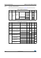
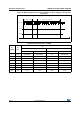
t
S
Sampling time
Direct channels
2.4 V ≤ V
DDA
≤ 3.6 V
0.25 - -
µs
Multiplexed channels
2.4 V ≤ V
DDA
≤ 3.6 V
0.56 - -
Direct channels
1.8 V ≤ V
DDA
≤ 2.4 V
0.56 - -
Multiplexed channels
1.8 V ≤ V
DDA
≤ 2.4 V
1- -
- 4 - 384 1/f
ADC
t
CONV
Total conversion time
(including sampling time)
f
ADC
= 16 MHz 1 - 24.75 µs
-
4 to 384 (sampling
phase) +12 (successive
approximation)
1/f
ADC
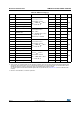
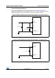
C
ADC
Internal sample and hold
capacitor
Direct channels -
16
-
pF
Multiplexed channels - -
f
TRIG
External trigger frequency
Regular sequencer
12-bit conversions - - Tconv+1 1/f
ADC
6/8/10-bit conversions - - Tconv 1/f
ADC
f
TRIG
External trigger frequency
Injected sequencer
12-bit conversions - - Tconv+2 1/f
ADC
6/8/10-bit conversions - - Tconv+1 1/f
ADC
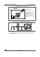
R
AIN
Signal source impedance - - - 50 κΩ
t
lat
Injection trigger conversion
latency
f
ADC
= 16 MHz 219 - 281 ns
-3.5-4.51/f
ADC
t
latr
Regular trigger conversion
latency
f
ADC
= 16 MHz 156 - 219 ns
-2.5-3.51/f
ADC
t
STAB
Power-up time - - - 3.5 µs
1. The V
REF+
input can be grounded iif neither the ADC nor the DAC are used (this allows to shut down an
external voltage reference).
2. The current consumption through V
REF
is composed of two parameters:
- one constant (max 300 µA)
- one variable (max 400 µA), only during sampling time + 2 first conversion pulses.
So, peak consumption is 300+400 = 700 µA and average consumption is 300 + [(4 sampling + 2) /16] x 400
= 450 µA at 1Msps
3. V
REF+
can be internally connected to V
DDA
and V
REF-
can be internally connected to V
SSA
, depending on
the package. Refer to Section 4: Pin descriptions for further details.
4. V
SSA
or V
REF-
must be tied to ground.
Table 54. ADC characteristics (continued)
Symbol Parameter Conditions Min Typ
Max Unit