
Datasheet


Revision history STM32L151x6/8/B, STM32L152x6/8/B
128/131 DocID17659 Rev 9
26-Oct-2012 7
Updated cover page.
Updated Section 3.10: ADC (analog-to-digital converter)
Updated Table 3: Functionalities depending on the operating power
supply range, added Table 4: CPU frequency range depending on
dynamic voltage scaling and Table 5: Working mode-dependent
functionalities (from Run/active down to standby).
Updated Table 27: Low-speed external user clock
characteristicsAdded footnote 2. in Table 14: Embedded reset and
power control block characteristics
Updated Table 22: Typical and maximum current consumptions in
Stop mode and Table 23: Typical and maximum current
consumptions in Standby mode
Updated footnote 4. in Table 22: Typical and maximum current
consumptions in Stop mode
Updated Table 44: I/O AC characteristics
Updated Table 47: I2C characteristics
Updated Table 49: SPI characteristics
Updated Section 6.3.9: Memory characteristics
Updated “non-robust” Table 54: ADC characteristics
Removed the note “position of 4.7 µf capacitor” in Section 6.1.6:
Power supply scheme
Updated Table 66: UFQFPN48 7 x 7 mm, 0.5 mm pitch, ultra thin
fine-pitch quad flat no-lead package mechanical data
Updated Table 65: LQFP48 7 x 7 mm, 48-pin low-profile quad flat
package mechanical data
Added the resistance of TFBGA in Table 69: Thermal characteristics
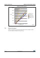
Added Figure 43: Thermal resistance
07-Feb-2013 8
Removed AHB1/AHB2 in Figure 1: Ultralow power STM32L15xxx
block diagram
Added IWDG and WWDG rows in Table 5: Working mode-
dependent functionalities (from Run/active down to standby).
Updated I
DD
(Supply current during wakeup time from Standby
mode) in Table 23: Typical and maximum current consumptions in
Standby mode
The comment "HSE = 16 MHz(2) (PLL ON for fHCLK above 16
MHz)" replaced by "fHSE = fHCLK up to 16 MHz included, fHSE =
fHCLK/2 above 16 MHz (PLL ON)(2)” in Table 19: Current
consumption in Sleep mode
Updated Stop mode current to
1.2 µA in Ultra-low-power platform
Updated entire Section 7: Package characteristics
Removed alternate function “I2C2_SMBA” for GPIO pin “PH2” in
Table 8: STM32L15xxx pin definitions
Updated Table 27: Typical connection diagram using the ADC and
definition of symbol “R
AIN
” in Table 54: ADC characteristics
Removed first sentence in I2C interface characteristics
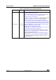
Table 71. Document revision history (continued)
Date Revision Changes