
Datasheet


DocID17659 Rev 9 99/131
STM32L151x6/8/B, STM32L152x6/8/B Electrical characteristics
105
General PCB design guidelines
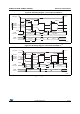
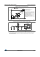
Power supply decoupling should be performed as shown in Figure 29 or Figure 30,
depending on whether V
REF+
is connected to V
DDA
or not. The 10 nF capacitors should be
ceramic (good quality). They should be placed as close as possible to the chip.
Figure 29. Power supply and reference decoupling (V
REF+
not connected to V
DDA
)
1. V
REF+
and V
REF–
inputs are available only on 100-pin packages.
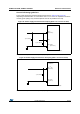
Figure 30. Power supply and reference decoupling (V
REF+
connected to V
DDA
)
1. V
REF+
and V
REF–
inputs are available only on 100-pin packages.
V
REF+
(see note 1)
STM32Lxx
V
DDA
V
SSA
/V
REF–
(see note 1)
1 μF // 100 nF
1 μF // 100 nF
ai17857b
V
REF+
/V
DDA
STM32Lxx
1 μF // 100 nF
V
REF–
/V
SSA
ai17858a
(See note 1)
(See note 1)