
Datasheet


DocID17659 Rev 9 73/131
STM32L151x6/8/B, STM32L152x6/8/B Electrical characteristics
105
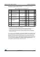
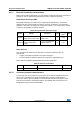
Note: For CL1 and CL2, it is recommended to use high-quality ceramic capacitors in the 5 pF to
15
pF range selected to match the requirements of the crystal or resonator (see Figure 18 ).
CL1 and CL2, are usually the same size. The crystal manufacturer typically specifies a load
capacitance which is the series combination of CL1 and CL2.
Load capacitance CL has the following formula: CL = CL1 x CL2 / (CL1 + CL2) + Cstray
where Cstray is the pin capacitance and board or trace PCB-related capacitance. Typically,
it is between 2 pF and 7 pF.
Caution: To avoid exceeding the maximum value of CL1 and CL2 (15 pF) it is strongly recommended
to use a resonator with a load capacitance CL ≤ 7 pF. Never use a resonator with a load
capacitance of 12.5 pF.
Example: if you choose a resonator with a load capacitance of CL = 6 pF and Cstray = 2 pF,
then CL1 = CL2 = 8 pF.
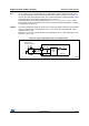
Figure 18. Typical application with a 32.768 kHz crystal
ai17853
OSC32_OUT
OSC32_IN
f
LSE
C
L1
R
F
STM32Lxx
32.768 kHz
resonator
C
L2
Resonator with
integrated capacitors
Bias
controlled
gain