
Datasheet


DocID17659 Rev 9 65/131
STM32L151x6/8/B, STM32L152x6/8/B Electrical characteristics
105
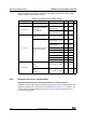
On-chip peripheral current consumption
The current consumption of the on-chip peripherals is given in the following table. The MCU
is placed under the following conditions:
• all I/O pins are in input mode with a static value at V
DD
or V
SS
(no load)
• all peripherals are disabled unless otherwise mentioned
• the given value is calculated by measuring the current consumption
– with all peripherals clocked off
– with only one peripheral clocked on
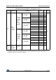
Table 23. Typical and maximum current consumptions in Standby mode
Symbol Parameter Conditions Typ
(1)
Max
(1)(2)
Unit
I
DD
(Standby
with RTC)
Supply current in Standby
mode with RTC enabled
RTC clocked by LSI (no
independent watchdog)
T
A
= -40 °C to 25 °C
V
DD
= 1.8 V
0.9 -
µA
T
A
= -40 °C to 25 °C 1.1 1.8
T
A
= 55 °C 1.42 2.5
T
A
= 85 °C 1.87 3
T
A
= 105 °C 2.78 5
RTC clocked by LSE (no
independent watchdog)
(3)
T
A
= -40 °C to 25 °C
V
DD
= 1.8 V
1-
T
A
= -40 °C to 25 °C 1.33 2.9
T
A
= 55 °C 1.59 3.4
T
A
= 85 °C 2.01 4.3
T
A
= 105 °C 3.27 6.3
I
DD
(Standby)
Supply current in Standby
mode with RTC disabled
Independent watchdog
and LSI enabled
T
A
= -40 °C to 25 °C 1.1 1.6
Independent watchdog
and LSI OFF
T
A
= -40 °C to 25 °C 0.3 0.55
T
A
= 55 °C 0.5 0.8
T
A
= 85 °C 1 1.7
T
A
= 105 °C 2.5 4
(4)
I
DD (WU
from
Standby)
RMS supply current during
wakeup time when exiting
from Standby mode
-
V
DD
= 3.0 V
T
A
= -40 °C to 25 °C
1-
1. The typical values are given for V
DD
= 3.0 V and max values are given for V
DD
= 3.6 V, unless otherwise specified.
2. Based on characterization, not tested in production, unless otherwise specified.
3. Based on characterization done with a 32.768 kHz crystal (MC306-G-06Q-32.768, manufacturer JFVNY) with two 6.8pF
loading capacitors.
4. Tested in production.